Derivation of the 32 Crystal Classes (Part One)
back to homepage
Introduction
In the Essays to come we will derive all the simple (in contradistinction to complex) Form types of each of the 32 Crystal Classes. A Form is a set of equivalent crystal faces. Real crystals generally are combinations of the Forms of the same Class.
But before we're going to do this we will first derive (albeit in a non-rigorous way) all the 32 symmetries that are possible for crystals to possess, the 32 Crystal Classes. In doing this we will make use of stereographic projections. In such projections -- See for the stereographic projection method the general Essay on The Morphology of Crystals -- the symmetries involved are easily detected and compared.
Before we actually do all this there are two more things to be done :
- Establishing the different categories (main types) of (point) symmetry.
- Derivation of the possible rotational symmetries in crystals.
In this Essay we will concentrate on the division of (point) symmetries into (1) rotation axes (rotational operations executed on a figure or its parts) and (2) roto-inversion axes (rotational operations combined with reflection in a point).
Establishing the different categories of (point) symmetry
Remark : A point symmetry is an operation performed on a figure such that at least one point remains where it was. On the contrary, a translational symmetry is an operation by which all points are moved to other locations. This translational symmetry is only evident on the atomic scale of a crystal because the translations (shifts) involved are very small indeed and not visible at the macroscopic level.
The 32 symmetry classes to be derived only concern the (32) point symmetries.
Symmetry can be defined as the property of a figure to consist of regularly repeated similar parts.
An asymmetric figure cannot be divided into similar parts.
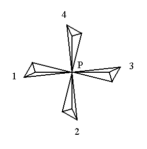
The figure (i.e. a configuration of parts) of Figure 1 consists of four similar parts, namely four (irregular) tetrahedra, that are regularly placed around a vertical (here perpendicular to the plane of the drawing) line through P.
 |
|
Figure 1.
A figure possessing 4-fold rotational symmetry. It consists of four similar parts which are mapped onto each other every 900 when the figure is rotated about a line perpendicular to the plane of the drawing and going through the point P (the center of the figure).
|
When we rotate the figure 900 about the vertical (i.e. perpendicular to the plane of the drawing) line through P the parts will be mapped onto each other, 1 on 2, 2 on 3, 3 on 4, and 4 on 1.
Also a rotation by a multiple of 900 will map the parts onto each other. Rotations that differ 3600, or a multiple thereof, from another rotation can be considered as identical, i.e. as one and the same rotation. So in our example there are just four different rotations that map the parts of the figure onto each other : 900 1800 2700 3600.
In the above Figure the parts are similar to each other in the way two right hands are. But it is also possible that the parts (of another figure) are similar in the way a right hand and a left hand are. A figure with such parts is depicted in Figure 2.
 |
|
Figure 2.
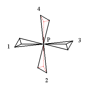
A figure possessing 4-fold roto-inversion symmetry. It consists of four similar parts which are mapped onto each other when the figure is rotated about a line perpendicular to the plane of the drawing and going through the point P (the center of the figure) immediately followed by an inversion in a point on the (4-fold roto-inversion) axis.
|
In Figure 2 we again see a configuration of four similar parts (irregular tetrahedra) but similar in a different way than they are in Figure 1.
1 and 3 and also 2 and 4 are similar as right hands are, but 1 and 2, and also 3 and 4 are similar in the way a right hand and a left hand are. 1 can be mapped onto 2 by a rotation of the figure by 900 clockwise about the vertical line through P immediately followed by an inversion in P. In the same way 2 will be mapped onto 3, 3 onto 4, and 4 onto 1.
Recall that inversion in a point (also called reflection in a point) of a part of the figure means that we draw straight lines from all the points of the part to the inversion point and extend each line with the same distance beyond that inversion point. The end points of those extensions then make up the image of the original part. We say that that image is an inversion of the original part.
In our case, however, the operation of inversion must be preceded by a rotation. The rotated part (which in our case is as such not a part of our initial figure nor of the figure finally resulting) must now be inverted in P, resulting in an image that is the inverted image of the rotated part. These two parts, the rotated part (which is as such -- I say it again -- in our case not a part of our initial whole figure nor of the whole figure finally resulting) and its inverted image together are now a configuration having a center of symmetry, meaning that this configuration is mapped onto it self by the operation of inversion as the next figure shows for a configuration of two crystal faces related to each other by a center of symmetry :
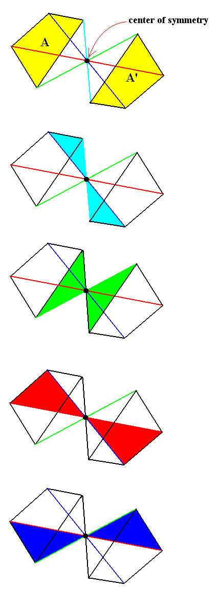
Figure 3. The symmetry of a face configuration, consisting of the faces A and A', consistent with a center of symmetry (cs).
In our case (Figure 2) we are concerned not just with an inversion, but with an inversion combined with a rotation. Although in this case inversion is involved, the whole figure (consisting of four parts) does not necessarily have a center of symmetry, and in our case it indeed does not have a center of symmetry.
The operation that in our case maps the parts of the figure onto each other is -- as has been said -- a combination of a rotation about a line and an inversion in a point on that line, a so called roto-inversion operation.
Of course the operations that map the parts of a figure onto each other also maps the whole figure onto itself.
So Symmetry is nowadays defined as the property of a figure that allows it to be mapped onto itself in more than one way. We speak of "more than one way" because every figure can always be mapped onto itself by the trivial operation : rotation by 3600 about any line.
The operations that can map a figure onto itself are called the symmetry operations of the figure.
We had examples of the two kinds of symmetry operations that can be encountered :
- Rotational operations
- Roto-inversion operations
The lines (or, when the case maybe, points or planes) with respect to which the symmetry operations are executed are called symmetry elements. So there also are two kinds of symmetry elements : rotation axes and roto-inversion axes (We will see that the other two conceivable kinds of symmetry elements, namely a center of symmetry and a mirror plane, are equivalent to a 1-fold roto-inversion axis and a 2-fold roto-inversion axis respectively).
The smallest (amount of) rotation, let's call it phi, associated with a symmetry element, must be a whole fraction of 3600, i.e. 360 = n.phi (where n is a whole number).
It this were not so, then there would be a p (p is a whole number) such that
(p -1)phi < 3600 < p.phi, ("<" signifies "smaller than") which means that when we multiply a rotation of phi0 by p we will end up a little beyond 3600. This 'little beyond 3600' is equal to p.phi - 3600, so p.phi - 3600 is the same rotation as p.phi.
The figure will be mapped onto itself by a rotation of phi0, so it will also be mapped onto itself by any multiple of phi, and thus also by p.phi, and consequently also by p.phi - 3600. Because (p -1)phi < 3600 < p.phi, p.phi - 3600 is smaller than phi. So we have a rotation, smaller than phi, that maps the figure onto itself, which is contrary to our initial assumption, namely that phi is the smallest rotation by which the figure is mapped onto itself. And when this p.phi - 3600 is itself again not a whole fraction of 3600 the story would repeat, etc. ...
Let us take as an example the assumption that 500 is the smallest (amount of) rotation that maps a figure onto itself (phi = 500). Then that figure will also be mapped onto itself by
8 x 500 = 4000. But a rotation of 4000 is the same as a rotation of 4000 - 3600, so a rotation of 400 will also map the figure onto itself, contrary to our initial assumption that 500 was the smallest rotation that would map the figure onto itself.
The whole number n in 360 = n.phi, where phi is the smallest rotation that maps the figure onto itself (in the case of rotation axes, and where it plays a similar but not wholly the same role in roto-inversion axes), is called the foldness of the symmetry axis or symmetry operation. In our Figures 1 and 2 we had to do with n = 4. In figure 1 we had a 4-fold rotation axis, and in Figure 2 we had a 4-fold roto-inversion axis.
Below we will prove that in crystals n can only be 1, 2, 3, 4, or 6.
n = 5, and n > 6 are not possible in crystals, because of their three-dimensional periodic structure.
A rotation axis is denoted by its number n, while a roto-inversion axis is denoted by its number n with a score above it. In the text of this website we will write such a roto-inversion axis as its n followed by an asterix.
So we have found the following ten symmetry elements that can occur in crystals :
1      1* (= i)
2      2* (= m)
3      3* (= 3 and i)
4      4*
6      6* (= 3 and m)
i stands for a center of symmetry.
m stands for a mirror plane.
The reader can check that 1* is equivalent to i, that 2* is equivalent to m, that 3* is equivalent to 3 + i and that 6* is equivalent to 3 + m.
Derivation of the possible rotational symmetries in crystals
In this and the next section we will make use of stereographic projections. As has been said, the reader should consult the section devoted to stereographic projections in the general Essay on The Morphology of Crystals if he or she is not familiar with them. With the help of the next Figure we will briefly recapitulate the projection method and the symbolism of stereograms, before we start with determining the possible values of n with respect to rotational symmetries in crystals.
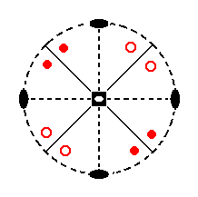
Figure 3a. Example of a stereogram.
Depicted is a stereographic projection of the symmetry elements of the Class 4* 2m , and of the face poles of the most general simple face configuration (Form) of that Class.
To obtain a stereographic projection of the symmetry elements and the faces of a crystal, the latter is placed in the center of a sphere.
To generate stereographic projections of the faces, perpendiculars are drawn from the center of the sphere onto the faces (representing their orientations). These perpendiculars are then extended till they intersect (pierce) the sphere. These piercing points are the so called face poles.
To obtain stereographic projections of the symmetry elements we extend all the symmetry axes of the crystal till they pierce the sphere and thus resulting in piercing points on the sphere. Further we extend the mirror planes of the crystal (if present in it) till they intersect with the sphere. Such a mirror plane is then represented on the sphere as a circle. In the case of an oblique mirror plane we only extend the part that lies above the equatorial plane (projection plane) resulting in half a circle on the sphere.
Now all these piercing points (and, when the case may be, circle halves), lying on the sphere, must be projected onto the equatorial plane (projection plane) of the sphere. This is done by connecting these points, when lying on the northern half of the sphere, with the south pole of that sphere. The intersections of those connecting lines with the equatorial plane (the projection plane) are now the stereographic projections of those points (lying initially) on the sphere, and at the same time they are the projections of the corresponding features of the crystal. Those (piercing) points that lie on the southern half of the sphere are connected with its north pole. Their intersections with the projection plane again are the projections of those points (lying initially) on the sphere, and at the same time they are the projections of the corresponding features of the crystal. (Piercing) Points on the equator of the sphere can be connected either with the south or the north pole, which does not make a difference. Their projections will end up om the perimeter of the equatorial plane.
In this way faces and axes are represented on the projection plane as points, a horizontal mirror plane as a circle coinciding with the perimeter of the projection plane, vertical mirror planes as straight lines. An inclined mirror plane then is represented on the projection plane as an arc (i.e. the hemicircle on the sphere becomes an arc on the projection plane).
The above Figure depicts the projection plane and the relevant projections onto it.
The fact that the circular outline of the projection plane is dashed means that a horizontal mirror plane is absent in the crystal. When such a mirror plane were present the outline would be drawn as a solid circular outline.
Two small solid ellipses opposite to each other signify a (horizontal) 2-fold rotatation axis.
The sign in the center of the projection plane signifies the vertical rotational axis, which in our example is a 4-fold roto-inversion axis.
The solid straight lines are the projections of vertical mirror planes (when a mirror plane is horizontal it will be projected as the just mentioned solid circular outline of the projection plane, when a mirror plane is inclined its projection will have the shape of an arc going from one side of the projection plane to the other).
The face poles of crystal faces (i.e. the piercing points of the perpendiculars to those faces) will end up as points on the projection plane. In our ensuing stereograms they will be depicted in red. When such a point was a projection from above (thus representing an upper face of the crystal), it will be depicted by a red dot (small solid red circle). When such a point was a projection from below (thus representing a lower face of the crystal), it will be depicted as a small red open circle. When there are two points on the sphere, one on the northern hemisphere and the other on the southern hemisphere, whose projections onto the projection plane coincide, they will be depicted as a small red circle centered with a red dot. When a face pole lies on the equator of the sphere (then representing a vertical face) its projection will end up on the perimeter of the projection plane, and will be given in the stereograms as small solid red circles. The same goes for piercing points of symmetry axes when those piercing points lie on the equator of the sphere. Their respective symbols come to lie on the perimeter of the projection plane. When an axis is inclined, one of its piercing points will come to lie on the northern hemisphere and the other on the southern hemisphere. In this case only the northern piercing point will be projected onto the projection plane, resulting in a point lying inward from the perimeter of the projection plane.
We shall now prove that the value of n, expressing the foldness of a rotation axis or of a roto-inversion axis, will be limited to 1, 2, 3, 4 and 6 in crystals because of their three-dimensional periodic structure.
The three-dimensional periodicity of a crystal is given by its translational lattice.
A translational lattice is a lattice of points such that every vector (a vector is a line of a certain length and having a certain direction) from a lattice point to another such point determines a parallel shift (translation) which maps the crystal's atomic piling pattern onto itself (when this pattern is conceived as being extended indefinitely).
Let a crystal possess a n-fold axis, then this axis will also be present in the translational lattice of that crystal. Perpendicular to a symmetry axis in a translational lattice is always a lattice plane of that lattice. In this lattice plane there is a shortest lattice vector, say p. In virtue of the n-fold axis there will be equal lattice distances in directions that make angles of
360/n0, 2 x 360/n0, ...(n - 1) x 360/n0 with p.
In figure 4, AB is the shortest lattice vector p.
p' = AC forms an angle with it of 360/n0 and p'' = AD an angle of (n - 1).360/n0 = -360/n0.
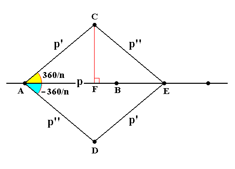
Figure 4. Some lattice points (of a lattice plane), separated by a minimum distance p (i.e. the length of the shortest translation vector p ). The lattice has n-fold symmetry.
Because AD represents a lattice vector, and thus a translation, E will be a lattice point if C is one -- and indeed it is one -- (i.e. from lattice point C we must find another lattice point at a distance equal to the length of AD and in the direction of AD, because the structure is repeated over distances equal to the length of p in the directions dictated by the n-fold axis. E lies on the line through AB. Because AB is the shortest translation all lattice points on the line through AB are separated by a distance equal to the length of p. So E, being a lattice point, should lie at a distance from A that is a whole number times the length of p (this length can be denoted by p). Then the following relation should hold :
AE = 2pcos(360/n) = Np (in which N is a whole number)
Let us derive this relation (See Figure 4).
Recall that the cosinus (cos) of an angle of a triangle having one other angle equal to 900 is equal to the ratio of the length of the opposite side and the length of the oblique side.
In figure 4 we have two angles at A, 360/n and -360/n. We can see that
cos(360/n) = AF/AC = AF/p
This is equivalent to
pcos(360/n) = AF
And now we can say :
AE = 2AF = 2pcos(360/n) = Np (in which N is a whole number)
This is equivalent to the equation
cos(360/n) = N/2
Now we can solve this equation for n.
We know that the cosinus of any angle varies only between -1 and 1.
Further we know that N is a whole (positive) number.
So we can proceed as follows :
If N = -2, then cos(360/n) is equal to -1, and this is the case when 360/n = 1800, and then n.180 = 360, so n = 2.
In the same way we can proceed for the other whole values of N such that the cosinus lies between -1 and 1 inclusive. Then we obtain the following solutions for n :
| N |
cos(360/n) |
360/n |
n |
| -2 |
-1 |
1800 |
2 |
| -1 |
-1/2 |
1200 |
3 |
| 0 |
0 |
900 |
4 |
| 1 |
1/2 |
600 |
6 |
| 2 |
1 |
00, 3600 |
1 (infinity) |
When n = 1 then a figure having a 1-fold axis will be mapped onto itself every 360/10 (= 3600).
When n = infinity then a figure having an infinity-fold axis will be mapped onto itself every 360/infinity0 (= 00).
Because a rotation of 3600 an one of 00 is a same rotation, a 1-fold axis is identical to an infinity-fold axis, so we can call them by the same name, say, a 1-fold axis.
So the table above has as its result that for crystals the value of n can only be 1, 2, 3, 4 or 6. These five values are also the only possible values for n with respect to roto-inversion axes. There a rotation is immediately followed by an inversion in a point on that axis. Let me explain.
An n-fold rotation axis generates a real image of the initial motif every 360/n0. But an n-fold roto-inversion axis does not always generate a real image every 360/n0. It generates either a real image every 360/n0, or an intermediate image every 360/n0. See the next Figures.
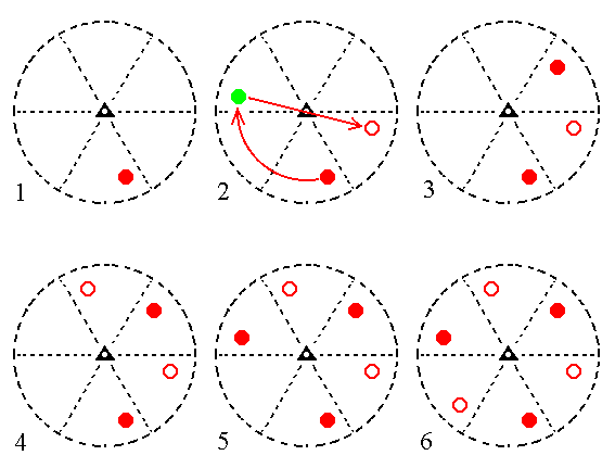
Figure 4a. Stages (1, 2, 3, 4, 5, 6) in the generation of a Form (i.e. a set of equivalent crystal faces) from an initial crystal face, by a 3-fold roto-inversion axis, depicted in stereographic projections (stereograms). Small red solid circles represent projections from above (so they represent upper crystal faces), small red open circles represent projections from below (so they represent lower crystal faces).
(1). Stereogram of the 3-fold roto-inversion axis and an initial motif (an upper crystal face).
(2). Illustration of the generation of a second crystal face by the action of the 3-fold roto-inversion axis.
The initial motif is rotated 1200 clockwise, generating an intermediate image (green dot). This intermediate image is then inverted through a point on the axis, resulting in the second crystal face, a lower face.
(3). In the same way a third crystal face can be generated from the second.
(4). Generation of the fourth face.
(5). Generation of the fifth face.
(6). Generation of the sixth face. This sixth face will generate the first face, i.e. the initial face, so after this no new faces are generated anymore.
In the end stage of the generation just given we see six crystal faces. They clearly show a 3-fold symmetry. Indeed we see an identical image appearing every 1200. So in this case a roto-inversion axis (here a 3-fold roto-inversion axis) successively replaces all the intermediary images (wherever they initially are generated) by real images. Indeed, a 3-fold roto-inversion axis is equivalent to a 3-fold rotation axis and a center of symmetry (Said in other words, a figure possessing a 3-fold roto-inversion axis which combines the operation of rotation with the operation of inversion in a point on that axis, is equivalent to it possessing a 3-fold rotation axis and possessing a center of symmetry).
Other roto-inversion axes are, however, not like that. They do not finally replace their intermediate images with real images, so for instance a 4-fold roto-inversion axis :
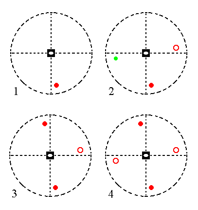
Figure 4b.
Stages (1, 2, 3, 4,) in the generation of a Form (i.e. a set of equivalent crystal faces) from an initial crystal face, by a 4-fold roto-inversion axis, depicted in stereographic projections (stereograms). Small red solid circles represent projections from above (so they represent upper crystal faces), small red open circles represent projections from below (so they represent lower crystal faces).
(1). Stereogram of a vertical 4-fold roto-inversion axis and an initial motif (an upper crystal face).
(2). Illustration of the generation of a second crystal face by the action of the 4-fold roto-inversion axis.
The initial motif is rotated 900 clockwise, generating an intermediate image (green dot). This intermediate image is then inverted through a point on the axis, resulting in the second crystal face, a lower face.
(3). In the same way a third crystal face can be generated from the second.
(4). Generation of the fourth face. This fourth face then generates the initial face, so no new faces are generated anymore when the process is continued.
The intermediate image in (2) of the above Figure stands for an upper (intermediate) crystal face, and, as can be seen, is not replaced by a real upper face.
Also in the case of a 6-fold roto-inversion axis the intermediate images are not replaced by real images :
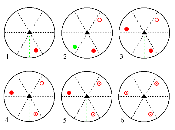
Figure 4c. Stages (1, 2, 3, 4, 5, 6) in the generation of a Form (i.e. a set of equivalent crystal faces) from an initial crystal face, by a 6-fold roto-inversion axis, depicted in stereographic projections (stereograms). Small red solid circles represent projections from above (so they represent upper crystal faces), small red open circles represent projections from below (so they represent lower crystal faces). A small red open circle centered with a red dot represents two coinciding projections, one from above and one from below.
(1). Stereogram of the 6-fold roto-inversion axis and an initial motif (an upper crystal face).
(2). Illustration of the generation of a second crystal face by the action of the 6-fold roto-inversion axis.
The initial motif is rotated 600 clockwise, generating an intermediate image (green dot). This intermediate image is then inverted through a point on the axis, resulting in the second crystal face, a lower face.
(3). In the same way a third crystal face can be generated from the second.
(4). Generation of the fourth face.
(5). Generation of the fifth face.
(6). Generation of the sixth face. This sixth face will generate a face that has already been generated before, so after this no new faces are generated anymore.
In the above Figure we see that there is no replacement of all the intermediate images. The final face configuration has a 3-fold symmetry. One can see that this face configuration could equally well be generated from the initial face by subjecting this face first to an ordinary 3-fold rotation axis, and then subject the result to the action of a horizontal mirror plane (indicated by the solid outline of the projection plane). So a 6-fold roto-inversion axis is equivalent to a 3-fold rotation axis plus a mirror plane perpendicular to it. Thus 6* = 3/m.
Above, Figure 4, we proved that only 1-, 2-, 3-, 4-, and 6-fold rotation axes can exist in crystals. This was based on the fact that the lattice points are being repeated in directions dictated by the rotational symmetry of the axis.
When we proceed to prove that the same values for n are also the only possible for roto-inversion axes then we must allow for the real as well as the intermediate images. And then the proof will go in exactly the same way as for the ordinary rotation axes, so we will find the same only possible values for n with respect to the roto-inversion axes.
This concludes our proof of the above given limited possibilities with respect to symmetry axes that can occur in crystals.
The symmetry of crystals can -- accordingly -- only be represented by those axes (namely 1-, 2-, 3-, 4-, and 6-fold rotation axes, and 1*-, 2*-, 3*-, 4*-, and 6*-fold roto-inversion axes), either occurring alone or combined, i.e. the symmetry of a crystal is either determined by such an axis or by a combination of them (a mirror plane (m) is equivalent to a 2-fold roto-inversion axis (2*), and a center of symmetry (i) is equivalent to a 1-fold roto-inversion axis (1*)).
It turns out that only 32 combinations (including symmetries determined by just one such axis) are possible. They represent the 32 Crystal Classes.
Derivation of the 32 Crystal Classes
We will now derive the 32 Crystal Classes (symmetry classes), albeit not rigorously, by means of stereographic projections.
We'll begin with a group of 27 Classes.
17 of them will be derived directly or indirectly from the remaining 10 which are represented by the above mentioned ten symmetry axes.
These 27 Classes will be ordered in a table having the following outline (In this outline (matrix) their corresponding entries are given in blue) :
| A 1 |
B 1 |
C 1 |
D 1 |
E 1 |
F 1 |
G 1 |
| A 2 |
B 2 |
C 2 |
D 2 |
E 2 |
F 2 |
G 2 |
| A 3 |
B 3 |
C 3 |
D 3 |
E 3 |
F 3 |
G 3 |
| A 4 |
B 4 |
C 4 |
D 4 |
E 4 |
F 4 |
G 4 |
| A 5 |
B 5 |
C 5 |
D 5 |
E 5 |
F 5 |
G 5 |
The above table only serves as a matrix of the possible entries of the ensuing real table of the stereograms of the (first to be discussed) 27 Crystal Classes (later to be supplemented with those of the remaining five Classes). Each stereogram in this real table represents a Class. It shows the symmetry elements of that Class and the projection of the face poles of the most general Form (i.e. it shows how a general face is multiplied by the symmetry elements of the relevant Crystal Class). Besides the relevant stereogram each entry of the table contains a sign indicating its position in the table, as given in the table outline above. The sign C 4 for instance indicates that the stereogram is located in the third column (column C) and in the fourth row of the table. Further we will add the symmetry symbol according to Hermann-Maugin, signifying the corresponding Crystal Class by its symmetry content (See for this notation the relevant SECTION in the general Essay on The Morphology of Crystals).
After having set up this overview of the first 27 Crystal Classes, we will then actually derive 17 of them from the first 10 Classes represented in the columns A and B.
The real table, depicting this overview now follows :
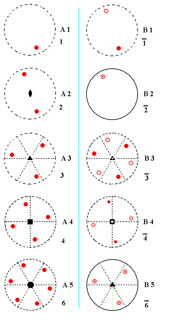
Figure 5. Overview of the first ten Crystal Classes in stereographic projection. They represent columns A and B of the matrix given above.
The next Figure continues this overview, depicting the columns C and D :
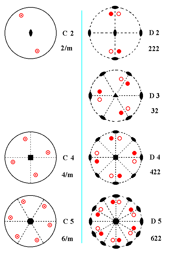
Figure 5a.Continuation of the Overview of the 27 Crystal Classes, columns C and D.
The Overview is further continued :
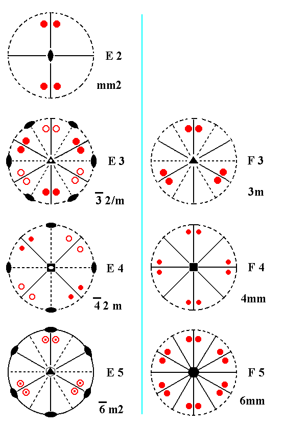
Figure 5b.Continuation of the Overview of the 27 Crystal Classes, columns E and F.
The Overview is finally finished :
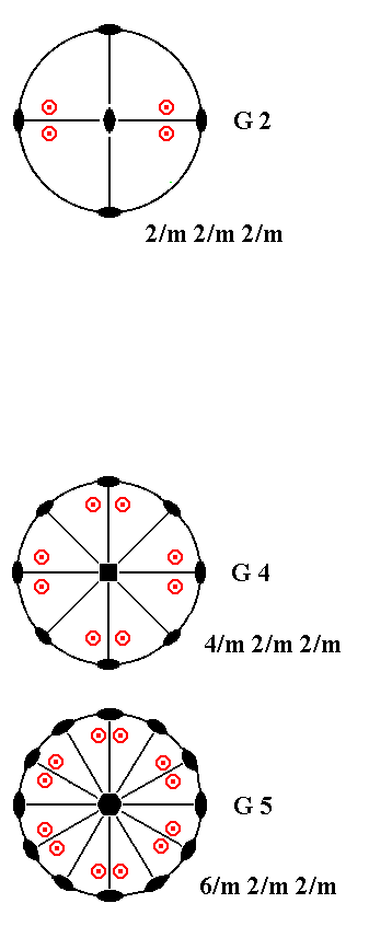
Figure 5c. Continuation and conclusion of the Overview of the 27 Crystal Classes, column G.
(A table concerning the five remaining Crystal Classes will follow later)
Now we are ready to actually derive 17 Classes of this table, from the first 10 Classes of that same table.
The Classes in the above table are symmetry combinations with at most one more-than-2-fold axis (the five remainig Classes have more than one more-than-2-fold axes). The stereograms are drawn such that the axis with the highest rotational symmetry is perpendicular to the plane of the drawing.
The first two columns (A and B) of the above table consist of Classes having just one symmetry axis (1-, 2-, 3-, 4- or 6-fold). This one axis is either a rotation axis or a roto-inversion axis.
In order to derive, from the Classes of these two columns, the remaining crystal classes of that table we must add symmetry elements to each of those ten Classes. When we look at the 27 Classes of the table, we see that the mirror planes, when present, are either horizontal or vertical, but never inclined (if they were, they would show up as arcs in the projections). The same goes for the 2-fold rotation axes (when they were inclined, they would not show up on the perimeter of the projection plane but inside it). If we would add a mirror plane or a 2-fold rotation axis that is inclined (i.e. neither vertical nor horizontal) then the vertical rotation axis will be multiplied by such an added mirror plane or added 2-fold rotation axis. And when that vertical axis were a more-than-2-fold axis, we would end up with more than one more-than-2-fold axes. So because we are at present concerned only with Classes (to be derived) that do not contain more than one more-than-2-fold axes, we cannot allow the addition of inclined symmetry axes or mirror planes to the symmetries that already contain a more-than-2-fold axis. So this addition is excluded with respect to row 3, 4, and 5 of the above table of stereographic projections.
For A1 and B1 the notion of "inclined" does not mean anything, because these two Classes do not have any directional element.
Addition of an inclined mirror plane or of an inclined 2-fold axis to those symmetries that do not contain any more-than-2-fold axis but do have directionality (in virtue of the presence of a 2-fold axis), will result in the multiplication of that 2-fold axis, and this axis will multiply the added mirror plane. This results in a more-than-2-fold rotational structure, with the new more-than-2-fold axis parallel to the plane of the drawing. But then we should (according to the accepted convention in our table) redraw the whole stereogram such that this more-than-2-fold axis becomes vertical, i.e. perpendicular to the plane of the drawing. But then we immediately see that the added symmetry elements (the mirror planes of 2-fold axes) are either perpendicular or parallel to the vertical axis. So we did not add inclined symmetry elements after all.
Consequently only the following (non-inclined) symmetry elements can be added to generate the Classes of the columns C, D, E, F and G of the above table, (ultimately) from the Classes of its columns A and B.
- center of symmetry
- a 2-fold rotation axis perpendicular to the n-fold axis
- a mirror plane parallel to the n-fold axis
- a mirror plane perpendicular to the n-fold axis
Indeed these symmetry elements are such that they map the vertical n-fold axis onto itself, and consequently do not multiply this axis, and so limit the Classes to be derived to our first group of 27 Classes in which at most one more-than-2-fold axis occurs.
In the ensuing derivations we will call the relevant Classes by their entries in the above table, thus as A1, A2, B1, etc.
Let's start with the addition of a center of symmetry to the Classes of column A.
In any face configuration that has a center of symmetry it is demanded that each face of that configuration must have an exactly oppositely situated parallel counter face such that these opposite faces can be mapped onto each other by the operation of inversion. In the next Figure the reader can see that inversion in a point is equivalent to a rotation by 1800 about a line going through that point followed by a reflection in a plane through that point perpendicular to the line. Said the other way around, reflection in a plane is equivalent to inversion in a point lying in that plane followed by a rotatation of 1800 about a line going through that point perpendicular to the mirror plane.
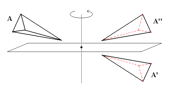
Figure 6. Inversion in a point is closely related to reflection in a plane.
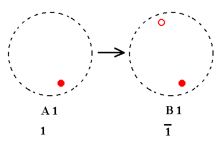
Addition of a center of symmetry to A1 yields B1. See Figure 7.
 |
|
Figure 7.
A1---B1
|
Because the Classes of columns A and B are the Classes from which we start our derivations -- i.e. those Classes are considered already present from the outset, based on our previous findings concerning the possible n-fold symmetry axes (rotation and roto-inversion axes) -- nothing new is generated by the just performed addition of a center of symmetry to A1.
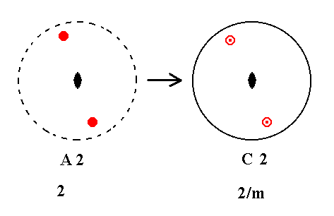
Addition of a center of symmetry to A2 yields C2. See Figure 8.
 |
|
Figure 8.
A2---C2
|
Here we have derived a new Class, namely the one having the entry C2 in our table. It is the class 2/m. Addition of a center of symmetry brought with it a horizontal mirror plane. This is because the inversion of a motif yields a mirror image of that motif when rotated 1800 (See Figure 6).
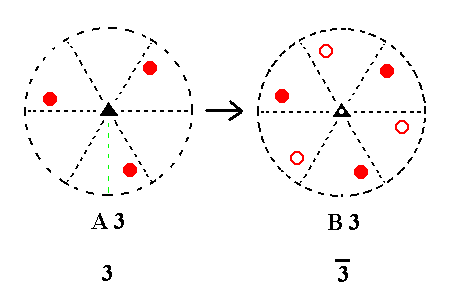
Addition of a center of symmetry to A3 yields B3. See Figure 9.
 |
|
Figure 9.
A3---B3
|
Addition of a center of symmetry generated the Class 3*, B3, so nothing new is generated.
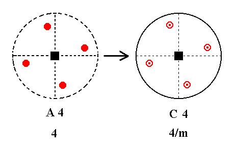
Addition of a center of symmetry to A4 yields C4. See Figure 10.
 |
|
Figure 10.
A4---C4
|
Inversion of a motif A yields a second motif A', that is the mirror image of another image of that initial motif A, generated when it is rotated 1800 (See Figure 6).
Here we have generated Class 4/m, C4, so we have derived a new Class.
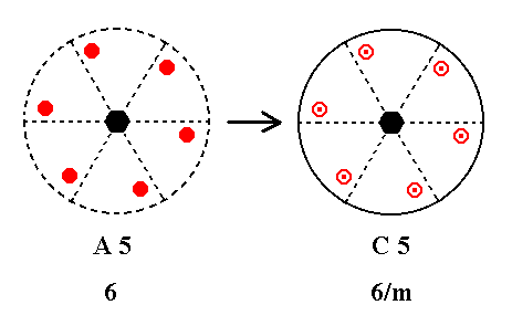
Addition of a center of symmetry to A5 yields C5. See Figure 11.
 |
|
Figure 11.
A5---C5
|
Inversion of a motif A yields a second motif A', that is the mirror image of another image of that initial motif A, generated when it is rotated 1800 (See Figure 6).
Here we have generated Class 6/m, C5, so we have derived a new Class.
So we have found the following new Classes, C2, C4, and C5.
Addition of a center of symmetry to the stereograms of column B has the same result as the addition of it to the stereograms of column A :
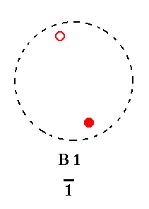
Addition of a center of symmetry to B1 yields B1, because B1 already has a center of symmetry. See Figure 12.
 |
|
Figure 12.
B1---B1
|
Addition of a center of symmetry to B2 yields C2.
Inversion is equivalent to a rotation of 1800 followed by a mirror reflection, as in Figure 6. So an initial upper motif generates first of all, in virtue of a rotation of 1800, an intermediate upper image horizontally opposite to it, and this image generates another image right beneath it in virtue of the mirror reflection. This new lower image is the real image of the inversion of the initial upper motif. The lower initial motif generates first of all an intermediate lower image horizontally opposite to it in virtue of a rotation of 1800, but this image was already a real image. Next this real lower image generates an image right above it. The resulting upper motif, which was already present as an intermediate image, is the real image of the intial lower motif when subjected to inversion. The total of motifs and images now adds up to four, and their configuration implies a 2-fold rotation axis, so this newly resulted configuration is consistent with a 2/m symmetry. See Figure 13.
 |
|
Figure 13.
B2---C2
Stages of the derivation of C2 from B2, by first a rotation followed by a reflection.
(1). Stereogram of the symmetry elements of the Class 2* (=m) and of the face poles of the most general Form.
(2). The upper initial motif is rotated 1800 generating an intermediate image upper image horizontally opposite of the initial motif.
(3). Reflection in a horizontal plane, resulting in a lower image, the real image of the inversion of the original upper motif.
(4). Rotation of the lower initial motif yields an intermediary lower image horizontally opposite to the initial lower motif.
(5). Reflection in a horizontal plane, resulting in an upper real image.
(6). This real upper image, together with the already generated lower real image, makes up two coinciding projections, one coming from above, one from below.
(7). The new face configuration implies a 2-fold rotation axis, and is consistent with 2/m symmetry.
|
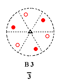
Addition of a center of symmetry to B3 does not have any effect on it, as can be seen by the distribution of the projection of the face poles. B3 already had a center of symmetry.
See Figure 14.
 |
|
Figure 14.
B3---B3
|
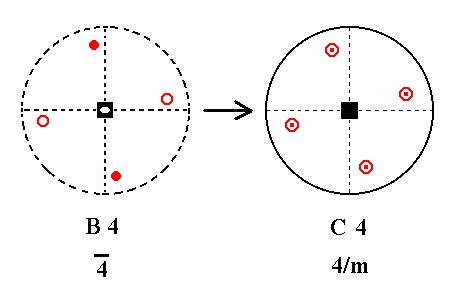
Addition of a center of symmetry to B4 yields C4.
Inversion of a motif A yields a second motif A', that is the mirror image of another image of that initial motif A, generated when it is rotated 1800. See Figure 15.
 |
|
Figure 15.
B4---C4
|
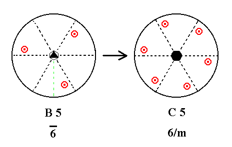
Finally, addition of a center of symmetry to B5 yields C5.
When an upper and lower motif together are subjected to inversion, another upper and lower motif are generated opposite to the initial pair, as explained in Figure 13. See Figure 16.
 |
|
Figure 16.
B5---C5
|
Indeed we have, by adding a center of symmetry, generated from the stereograms of column B the following 'new' Classes : C2, C4, and C5. And these we had already derived from column A.
To continue, click HERE for Part Two.
back to homepage
****************


