(a O b) O c = a O (b O c). So it does not matter if we first put a and b together (according to the operation O and then "add" c (again according to the operation O), or if we take a and then "add" (b O c).
We must notice that the second Group Axiom does not demand that the operation should be commutative (An operation X is commutative if the following applies :
a X b = b X a ).
From the Group Axioms all kinds of theorems can be deduced.
Let us now see how symmetry is described by a Group.
As an example we take a (two-dimensional) object that has only four-fold rotational symmetry, i.e. its symmetry consists of only (in order to have a simple example) one symmetry element, namely a 4-fold rotation axis :
This four-fold symmetry means that if we rotate the object 90 degrees, or a multiple thereof, about the axis (thought to be perpendicular to the plane of the structure) going through the central point, then we obtain the same object again, also having the same orientation as it had before the rotation was carried out, i.e. the resulting object exactly covers the original object.
We can now describe this symmetry (of the above object) by a Group :
The SET of group elements is the set of possible rotations (rotations that transform the object into itself). They are :
- 0 degrees (equivalent to 360 degrees)
- 90 degrees.
- 180 degrees.
- 270 degrees.
The group OPERATION is :
The combination of two rotations (i.e. the combination of two elements of the group SET).
"To combine two rotations A and B" here means :
First subject the object to a rotation A, and then, continuing with the result, subject it to rotation B. We can denote the group operation by the symbol +.
In our case we could for example subject the above object first to a rotation (about the axis mentioned) of 90 degrees, and then rotate the result, say, 180 degrees. This will result in a rotation of 90+180=270 degrees.
If we subject our object first to a rotation of 180 degrees and then to a rotation of 270 degrees, then we have in fact rotated the object 180+270=450 degrees, but such a rotation (of 450 degrees) is equivalent to a rotation of 450-360=90 degrees, so 180+270=90, i.e. group element "180 degrees rotation", combined (according to the operation +) with group element "270 degrees rotation" results in "90 degrees rotation", which itself turns out to be an element of the group set.
We can now display this Group (describing the 4-fold symmetry of our object) in the form of an operation table, that depicts all possible combinations of the group elements according to the operation +. We can easily see that every possible operation results in an element already present in the group set :
| + | 0 | 90 | 180 | 270 |
| 0 | 0 | 90 | 180 | 270 |
| 90 | 90 | 180 | 270 | 0 |
| 180 | 180 | 270 | 0 | 90 |
| 270 | 270 | 0 | 90 | 180 |
Crystal Classes and Crystal Systems
Crystals can be classified in 32 Crystal Classes (Symmetry Classes) according to their symmetry content (point symmetry), which means that each Crystal Class is characterized by a specific "bundle" of symmetries. So each crystal belonging to a certain Crystal Class displays a specific set of symmetries. In fact we should say that such a crystal holds a specific set of (point) symmetry elements. There are several basic types of symmetry elements : rotation axes, mirror planes, center of symmetry. So a symmetry element is for example a four-fold rotation axis, a three-fold rotation axis, a primary mirror plane, a secondary mirror plane, etc.Symmetry can also be expressed using roto-inversion axes (= rotation, direcly followed by an inversion {= reflection in a point}) leading to notations, nowadays widely used in symbolizing Crystal Classes.
But here in this Essay we will use the classical way of expressing symmetry and symmetry bundles, because it is intuitively more directly accessible. There is however one exception.
It is the 4-fold roto-inversion axis, which turned out to be a unique and independent symmetry element.
The Set of Basic Symmetry Elements is :
1-fold rotation axis.
2-fold rotation axis.
3-fold rotation axis.
4-fold rotation axis.
6-fold rotation axis.
mirror plane.
center of symmetry.
4-fold roto-inversion axis.
Of course every object whatsoever contains a 1-fold rotation axis, because every object will be transformed into itself by such a rotation (which is : a 360 degrees rotation of the object). If a 1-fold rotation axis is the only symmetry operation that the object allows (in order that it will be transformed into itself) then such an object has in fact no symmetry at all, it is totally asymmetric.
The next images portray seven of these eight basic symmetry elements :
Figure 1. Basic Symmetry Elements.
The five types of rotation axes, and a mirror plane (m).
The red lines (thought to be perpendicular to the plane of the screen) in the images expressing rotational symmetry, indicate that the axis is polar (p) in order to assure that these figures depict rotational symmetry only.
The red line (also thought to be perpendicular to the plane of the screen) in the image expressing mirror symmetry, is also a polar axis (p) and serves to garantee that the image dipicts mirror symmetry only.
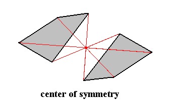
Figure 2. The seventh basic symmetry element : center of symmetry.
The item possessing a center of symmetry (and only a center of symmetry) consists of two asymmetric faces related to each other by a center of symmetry, which means that every point of such a face is reflected in a same point, the center of symmetry (indicated by the red lines and their point of intersection. Every part of the item can also be found at the opposite side of that point at the same distance.
The eighth basic symmetry element is the 4-fold roto-inversion axis. For an object to have a 4-fold roto-inversion axis means that the object will be transformed into itself again when subjected to the following operation : a rotation of 90 degrees immediately followed by an inversion (reflection) with respect to a point on the axis. Notice that possessing such a 4-fold roto-inversion axis does not necessarily imply the possession of a center of symmetry. In the case of a 4-fold roto-inversion axis the inversion (with respect to a point on the axis) is only a part of a symmetry operation. The inversion always comes after a rotation of 900, so there need not to be counterparts (counter faces) with respect to this point and consequently no center of symmetry. Let us dwell on this a little more. When we consider an initial crystal face on a crystal that possesses this axis, then the face generated by subjecting this initial face to the workings of this axis must also be present on that crystal. To produce this face we rotate the initial face 900 and directly reflect the imaginary result (of that rotation) with respect to a point on the axis (inversion). This results in the new face. The only items that are related to each other by an inversion are the imaginary intermediate stage (of the operation) and its end product, the new face. And only the initial face and the new face are real, i.e. really generated (the initial face can be generated in the same way), and they do not relate to each other by an inversion.
In fact this 4-fold roto-inversion axis is a 2-fold rotation axis of a special type. It is moreover equivalent with a so called 4-fold alternating axis (in German : vier-zählige Drehspiegel Achse). Turning the crystal through a quarter turn about an axis, and then reflecting it in the plane perpendicular to that axis, is the symmety operation corresponding to a 4-fold alternating axis (HOLDEN & MORRISON, 1982, Crystals and Crystal Growing, p. 285).
The 4-fold roto-inversion axis is normally written as a 4 with a score above it, but we, on this website, will, because of typographical problems, write it as 4*.
Remark : In addition to the 4-fold roto-inversion axis it is possible to recognize a 1-fold roto-inversion axis, a 2-fold roto-inversion axis, a 3-fold roto-inversion axis and a 6-fold roto-inversion axis (resp. 1*, 2*, 3* and 6*). Their workings are analogous to that of the 4-fold roto-inversion axis. But they are not representing any new, i.e. additional, basic symmetry elements, because the 1* axis is equivalent to a center of symmetry, the 2* axis is equivalent to a (horizontal) mirror plane, the 3* axis is equivalent to a combination of a 3-fold rotation axis and a center of symmetry, and 6* is equivalent to a combination of a 3-fold rotation axis and a mirror plane.
These basic symmetry elements can be combined (yielding composites of them).
It turns out that there are precisely 32 unique combinations possible, including the basic symmetry elements on their own, which means that, say, just a three-fold rotation axis is also to be counted as such a combination.
Those 32 combinations represent the 32 Point Groups or Crystal Classes.
So each Crystal Class represents a specific set of symmetry elements. For example crystals of the Cubic Hexakisoctahedral Crystal Class possess the following (total of) symmetry elements, or, in other words, the following combination of basic symmetry elements :
Three 4-fold rotation axes, coincident with the three crystallographic axes.
Four 3-fold rotation axes, in diagonal directions.
Six 2-fold rotation axes, bisecting the angles between the crystallographic axes.
Three primary mirror planes (symmetry planes), each one parallel to two crystallographic axes.
Six secondary mirror planes (symmetry planes), bisecting the angle between two primary mirror planes while perpendicular to a third.
Center of symmetry.
The Crystal Classes (Symmetry Classes) can be named in two ways.
- After the name of the most general Form.
For example, the most general Form of the highest symmetrical Class of the Cubic System (Isometric System) is the Hexakisoctahedron, so this Class is called the (Cubic) Hexakisoctahedral Class. - After the degree of completeness of the set of mirror planes present in the Class.
The highest symmetrical Class of a Crystal System contains (by definition) the complete set of mirror planes. The lower symmetrical Classes of that System each contain only a part of this set. For example, the highest symmetrical Class of the Cubic System is (also) called the Holohedric Class (or Holohedric Division), while the Gyroidic Class of that System can (also) be called the Plagihedric Hemihedric Class (or Division), in which "Plagihedric" refers to which mirror planes are missing with respect to the set of those planes present in the Holohedric Class (We will explain these concepts below).
- 1-fold rotation axis. symbol : none.
- 1-fold roto-inversion axis. symbol : 1* (In the literature it is denoted by a 1 and above it a horizontal score)
- mirror plane. symbol : m
- 2-fold rotation axis. symbol : 2
- 3-fold roto-inversion axis. symbol : 3*
- 3-fold rotation axis. symbol : 3
- 4-fold roto-inversion axis. symbol : 4*
- 4-fold rotation axis. symbol : 4
- 6-fold roto-inversion axis. symbol : 6*
- 6-fold rotation axis. symbol : 6
The Hermann-Mauguin symbol of a Crystal Class consists of one, two or three parts, that relate to the following directions [For the Crystal Systems and the crystallographic axes (i.e. a-axis, b-axis, etc.) mentioned in the table, see below ] :
| Crystal System |
First Part | Second Part | Third Part |
| Monoclinic |
Ortho-axis | - | - |
| Orthorhombic |
a-axis | b-axis | c-axis |
| Tetragonal |
c-axis | a- and b-axis | bisectors between a- and b-axes |
| Hexagonal |
c-axis | a-, b- and d-axis | bisectors betw. a-, b- and d-axes |
| Isometric |
a-, b- and c-axis | body-diagonals | plane-diagonals |
Regarding the Isometric System : Body-diagonals are lines perpendicular to the octahedral faces, while plane-diagonals are lines that are parallel to one of the cube faces.
Regarding the Monoclinic System : The Ortho-axis is the crystallographic axis of the Monoclinic System that is perpendicular to the two other monoclinic crystallographic axes.
Regarding the Triclinic System : It consists of only two Classes, having respectively 1 and 1* as their Hermann-Mauguin symbols.
Let us treat another example.
The symbol 4/m 2/m 2/m refers to a tetragonal crystal (i.e. a crystal belonging to the Tetragonal Crystal System) [ 4 also occurs in the isometric Classes, but (the symbols for) such crystals are directly recognized by the 3 at the second part of the symbol]. This Class has a 4-fold rotation axis along the c-axis and a mirror plane perpendicular to it, so 4/m comes as the first part of the symbol. It has moreover 2-fold rotation axes along the a- and b-axes, each of them having a mirror plane perpendicular to it, so 2/m will figure as the second part of the symbol (there are two such rotation axes (coupled with a mirror plane), but, because they are equivalent they are represented in the symbol by only one "2/m"). Further the Class has two more 2-fold rotation axes along the bisectors of the a- and b-axes, and a mirror plane perpendicular to each one. So they are also represented by 2/m, which however will figure as the third part of the Hermann-Maugin symbol of the Class.
Sometimes the Hermann-Maugin symbols are used in an abbreviated form, namely in those cases where some symmetry elements are implied by others. The implied ones are then omitted if there is no possibility of confusion. On this website we will, however, always use the complete symbols.
When we come to treat of the 32 Crystal Classes these symbols will be used, and, along with it, better understood.
Because of several similarities obtaining between certain Crystal Classes the 32 Classes can be grouped into several collections, the Crystal Systems (although the Crystal Classes are completely independent). There are six such Crystal Systems (They will be individually expounded in subsequent Essays) :
- The CUBIC system (also called the Isometric System).
- The TETRAGONAL system.
- The ORTHORHOMBIC system.
- The MONOCLINIC system.
- The TRICLINIC system.
- The HEXAGONAL system.
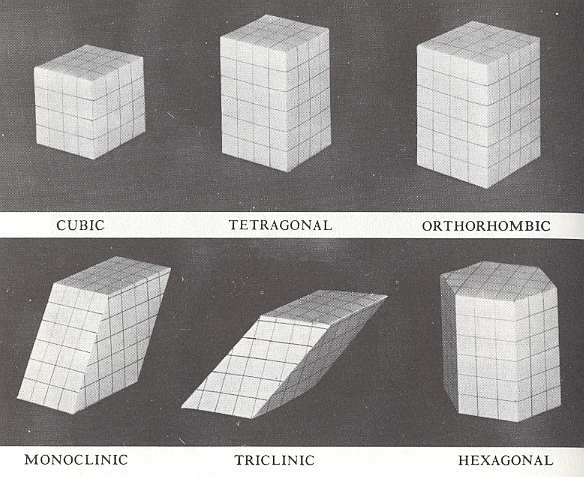
Figure 3. The Six Crystal Systems
(After HOLDEN & MORRRISON, Crystals and Crystal Growing, 1982)
In the figure we can see that there are six styles of crystalline architecture, each employing a different sort of building block. And every crystal belongs to one of these six "crystal systems". Lines are drawn in these models to assist in visualizing which angles are right angles and which are not.
In the CUBIC block all angles are right angles and all sides are equal.
In the TETRAGONAL block all angles are right angles but there are two different lengths of side.
In the ORTHORHOMBIC block all angles are right angles but there are three different lengths of side.
The MONOCLINIC block is like the orthorhombic block, pushed so eight of its angles are no longer right angles.
In the TRICLINIC block there is no right angle and there are three different lengths of side.
The HEXAGONAL block is a hexagonal prism, with right angles between its vertical sides and its top and bottom faces. (After HOLDEN & MORRISON).
So the Crystal Systems are based on the outer form of the building block of the crystal. When considering just its outer form the building block has the same symmetry as the highest symmetrical class of the relevant Crystal System. The building block is repeated in three directions and in this way (conceptually) builds up the crystal.
The Method of describing Crystal Faces and Basic Forms
The morphology of crystals, especially the orientation of its faces, can be described by relating all this to an appropriate set of axes. These axes are chosen in such a way that each one of them is parallel to a certain conspicuous crystal edge (for cubic crystals for example, the axes are chosen such that they correspond to three edges of the cube that are perpendicular to each other. In this case we then obtain three equivalent axes that are perpendicular to each other). For other types of crystals some other sets of axes are appropriate. Such axes are called the crystallographic axes.In the figure below we see an example of a set of three crystallographic axes. We also see two polyhedra, two different double pyramids (bipyramids). For both of them their upper right face is marked with a gray color.
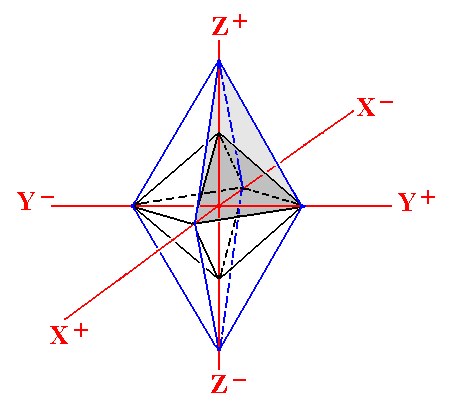
Figure 4. A set of three crystallographic axes and two bipyramids with their geometrical centers coinciding with the origin of the system of axes. Of each bipyramid one of their faces is marked with a grade of gray. The faces cut off certain pieces of the axes.
Here the vertical axis is called the Z-axis, the axis that is more or less pointing to the observer is called the X-axis, while the one that is aligned East-West is called the Y-axis. Each axis is divided into two parts by the origin of this set of axis, and those parts are interpreted as negative (-) or positive (+) as indicated in the figure.
A face of a polyhedron (and so also a crystal) can cut off a segment from either all three axes, or from two of them (and then being parallel to a third axis), or from only one of them (and then being parallel to the two other axes). In the above figure each face cuts off a piece from all three axes, i.e. it is not parallel to any one of them.
Remark : In the different Crystal Systems different axial systems are used, involving different angles and sometimes more than three axes.
Parameter ratio
If we consider a face (of a crystal) in its relation with a set of crystallographic axes, like the one pictured above, we can measure the cut-off pieces (intercepts) of those axes, pieces cut off from those axes by that particular face. We shall denote the piece cut off from the X-axis as a, the piece cut off from the Y-axis as b and the piece cut off from the Z-axis as c.Because parallel faces are crystallographically equivalent (they have exactly the same orientation), the absolute lengths of the cut-off pieces are not important. What is important (to describe the orientation of the face) is their ratio. So we set the length of one of them, b, equal to 1, and determine the lengths of the other pieces (the cut-off piece of the X-axis, a, and the cut-off piece of the Z-axis, c) relative with respect to b. In this way we obtain, with respect to the above set of axes, three numbers, and their ratio we call the parameter ratio of that particular crystal face.
Description of crystal faces, and the generation of "basic Forms"
To describe each face of a crystal species belonging to a certain Crystal Class (thus possessing a certain symmetry (content)) we first of all choose a conspicuous face (conspicuous by, say, some physical properties like luster) which cuts off all three axes at a finite distance from the origin of the axes system. We will call such a face the unit face of the particular crystal class. We measure the parameter ratio of that face. Then we measure the parameter ratios of all other faces of the same crystal (species). Next we relate the latter measurement results to those of the unit face. If we denote the parameter ratio of this unit face as a : b : c then we can express the other faces in the same way, but now provided with numbers in front of each letter (i.e. coefficients), to express their orientation relative to the unit face (and thus relative to the crystallographic axes). In crystals these numbers turn out always to be rational numbers, i.e. numbers like 1/2, 1/3, 1, 3, 5, etc., and not irrational numbers like the square root of 2, or whatever number with a floating point like 2.54728..., or 0.445106..., etc.Now if we take the gray shaded face of the smaller bipyramid in Figure 4 as unit face with respect to this particular type of axis system, we can describe all the faces depicted in Figure 4. We will denote the unit face by a : b : c. All other faces of the smaller bipyramid can be symbolized in the same way (because they are assumed to involve cut-off pieces (intercepts) of the same respective lengths as the (corresponding) ones of the unit face) except for their signs (+ or -). So the face just below the unit face can be denoted by a : b : -c.
The gray shaded face of the larger bipyramid cuts off twice as much from the Z-axis than the unit face does, but the same (amount) from the X-axis and from the Y-axis as the unit face does. So we can denote this face as a : b : 2c.
If the larger bipyramid were steeper then this face could be denoted by say, a : b : 3c.
If the steepness of the face increases more and more it will eventually become parallel to the Z-axis, which means that its cut-off point lies infinitely far away from the origin of the set of axes. So the coefficient in front of c becomes infinitely large and will be denoted by the sign ~. Thus if indeed that face assumed a vertical position (it could then belong to a prism instead of a bipyramid) then (still relating this face to the unit face) it could be describes as a : b : ~c.
If we imagine a face that cuts off a piece of the Z-axis twice as long as the unit face does but which is horizontally oriented, then it is parallel to both the X-axis and the Y-axis, so the symbol for this face would read ~a : ~b : 2c. And if it were parallel to both the X-axis and the Z-axis then its symbol would read ~a : b : ~c.
If the cut-off piece concerns a part of the axis which is negative (-) then the symbol - will be placed in front of the symbol corresponding to that particular axis. For example ~a : ~b : -2c denotes a face which goes through the lower tip of the larger bipyramid of Figure 2, but is parallel to both the X-axis and the Y-axis.
When we consider a certain face of a crystal, belonging to a certain Crystal Class, in isolation, then we can subject this one face to all the symmetry operations (rotatation, reflection, etc.) of that Crystal Class (In fact this is equivalent to the demand that precisely those symmetries must finally all be present in the finished structure having the crystallographic axes as its scaffold). Generally we then will obtain more faces, in virtue of the workings of those symmetries. For instance the presence (i.e. the operation) of a mirror plane (as belonging to the set of symmetry elements of that particular Crystal Class) will normally duplicate that face (except when that mirror plane is perpendicular to that face). If that mirror plane is parallel to that face then we will obtain a pair of parallel faces.
The structure, resulting from subjecting a particular face to all the symmetry elements (i.e. symmetry operations) of the relevant Crystal Class, is called a (basic) Form. Such a Form could be something that completely encloses a volume of space within its faces like a cube or an octahedron, or it could be open, like a prism without bottom and top faces, or just a pair of faces. It even could be one face only, namely in the case where the Crystal Class does not have any symmetry at all, like the Triclinic Pedial Crystal Class. Of course the open Forms cannot exist as real crystals, but should be combined with other Forms.
So while the familiar meaning of the term Form refers to the outward appearance of something, its meaning in Crystallography is somewhat different and more restricted (the outward appearance is indicated by the term habit):
A Form consists of a group of crystal faces, all of which have the same relation to the elements of symmetry and display the same chemical and physical properties because all are underlain by like atoms in the same geometrical arrangement.
A Form will be denoted by one of its faces, namely the one with positive coefficients, like a : b : c. To denote the Form we place this symbol between brackets : (a : b : c).
The shapes of Crystals belonging to a certain Crystal Class can be those closed Forms and also any combination of whatever Forms belonging to that Crystal Class.
An example of the derivation of Forms
It is now possible to derive the crystal Forms and their combinations and thus all crystal shapes (of ideally grown crystals).We shall work out some examples with respect to the Isometric System.
The Forms (and their combinations) of Crystals belonging to the Isometric System can be described by means of a set of three equivalent crystallographic axes perpendicular to each other :
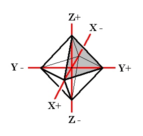
Figure 5. Basic Form (regular octahedron) of the Isometric Crystal System, and the set of crystallographic Isometric axes.
In this Figure we have drawn the basic Form of the Isometric Crystal System, the regular octahedron. One face is shaded. This face cuts off equal pieces of the three crystallographic axes, and can accordingly be denoted by a : a : a, in which the three a's express the fact that the three axes are equivalent.
We will now derive some Forms belonging to the most symmetrical Crystal Class of the Isometric System, the Cubic Hexakisoctahedral Crystal Class.
Recall that the symmetry content of crystals of this Class is :
Three 4-fold rotation axes, coincident with the three crystallographic axes.
Four 3-fold rotation axes, in diagonal directions.
Six 2-fold rotation axes, bisecting the angles between the crystallographic axes.
Three primary mirror planes (symmetry planes), each one parallel to two crystallographic axes.
Six secondary mirror planes (symmetry planes), bisecting the angle between two primary mirror planes while perpendicular to a third.
Center of symmetry.
Let us depict some symmetry elements of this Class (Figures 6, 7 and 8) :
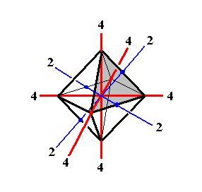
Figure 6. Some symmetry elements of the Cubic Hexakisoctahedral Class. Depicted : All three 4-fold rotation axes (4), and two (out of six) 2-fold rotation axes (2).
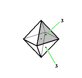
Figure 7. Some symmetry elements of the Cubic Hexakisoctahedral Class. Depicted : two (out of four) 3-fold rotatation axes (3).
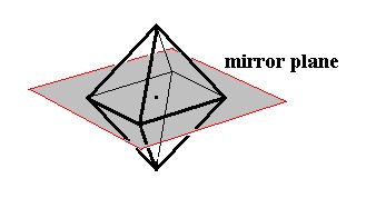
Figure 8. Some symmetry elements of the Cubic Hexakisoctahedral Class. Depicted : one (out of nine) mirror plane, and center of symmetry (represented by the dot in the middle of the image).
In explaining the faces and Forms we concentrate on the notational method described above. This is the method of Chr. WEISS.
There are two other, equivalent methods, one developed by C. NAUMANN and another by W. H. MILLER. They will be explained below.
Now if we consider the shaded face (which is the unit face for the Isometric Crystal System) in Figure 5 in isolation, i.e. if we think of having only this one face, then we can generate the complete Form (the regular octahedron of Figure 5) when we subject this face to all the symmetry elements (symmetry operations) belonging to our Crystal Class, here the Cubic Hexakisoctahedral Crystal Class (resulting in the finished form having all the symmetries of that Class) :
A vertical 4-fold rotation axis then generates (starting from the one face mentioned) the upper part of the regular octahedron (to subject our face to this four-fold rotational symmetry will result in the generation of the three others). The horizontal mirror plane, coinciding with the plane in which the X and Y axes lie, will generate (from the top half we now have) the bottom half of the octahedron. So we now have our complete octahedron. All the remaining symmetries are by now already implied, i.e. when we subject our regular octahedron to those remaining symmetry operations no new faces are generated anymore. The generated regular octahedron possesses all the symmetries of the Cubic Hexakisoctahedral Class. The Weiss symbol for the regular octahedron (the basic Form of the Cubic Hexakisoctahedral Crystal Class) is:
(a : a : a), the Naumann symbol is O., and the Miller symbol is {111}. (Recall that these symbols are equivalent, it's just a difference in the method of description of faces and Forms).
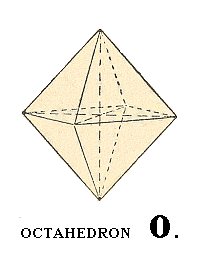
Figure 9. Regular octahedron.
A next basic Form of this Class is the cube.
To accomplish its derivation we let the shaded face of Figure 5 become more and more steep, which means that the length of the cut-off piece of the Z-axis becomes bigger and bigger. In the limit this piece becomes infinitely long. The face has now aquired a vertical position. Next we turn this vertical face such that it becomes parallel to the X and Z axes (while remaning vertical). In this way we obtain the face of a cube (oriented correctly), namely its right vertical face, and this face can be denoted by : a : ~a : ~a.
If we now subject this vertical face to the symmetry elements of our Class then a cube will be generated : The vertical 4-fold rotation axis will result in the four vertical faces of the cube, and a secondary mirror plane (demanded to be present in the finished structure) stretching between diametrically opposite horizontal edges of the until now generated structure generates the top and bottom faces of the cube. The figure we thus have generated not only is a cube, but also one with a convenient orientation : The crystallographic axes still coincide (as in the case of the above generated octahedron, the basic Form) with 4-fold axes. The Weiss symbol for the cube (= regular hexahedron) is :
(a : ~a : ~a), the Naumann symbol is ~O~., and the Miller symbol is {100}.
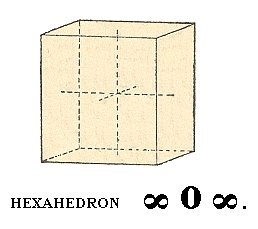
Figure 10. Cube, or regular hexahedron.
A next basic Form of this Class to be derived is the rhombic dodecahedron.
To accomplish this we let the shaded face of Figure 5 become vertical. This face can then accordingly be denoted by a : a : ~a. When we now subject this face to the symmetry elements of our Crystal Class we obtain a rhombic dodecahedron :
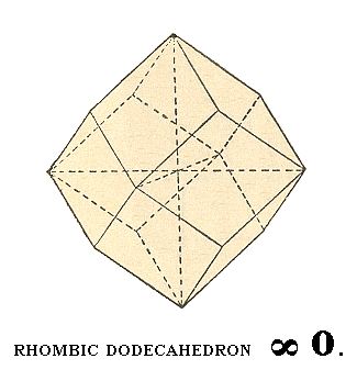
Figure 9. Another basic Form of the Cubic Hexakisoctahedral Crystal Class, the rhombic dodecahedron.
The Weiss symbol for this Form is accordingly :
(a : a : ~a), the Naumann symbol is ~O., and the Miller symbol is {101}.
Another Form of this Class is the ikositetrahedron.
We can derive this Form as follows :
Starting again with the shaded face of the regular octahedron of Figure 5, we will let it turn horizontally such that the length of the cut-off piece of the Y-axis (i.e. the length of the piece cut off from the Y-axis by that face) has been increased, without having this increase carried to an extreme (meaning that the length of the cut-off piece does not become infinite). Many such positions of the face are possible, for example a case in which the cut-off piece of the Y-axis has become twice as long as the one of the X-axis. Here we will consider the general case, and say that the cut-off piece of the Y-axis has become m times as long as the one of the X-axis.
The symbol of the face would then read : a : ma : a. Next we are going to further subject the face a : ma : a to a turn such that the length of the cut-off piece of the Z-axis increases in precisely the same way as the cut-off piece of the Y-axis did before. The resulting face can then be described with the symbol : a : ma : ma.
If we now subject this face to all the symmetries of our Crystal Class, a polyhedron will be generated that is called an ikositetrahedron :
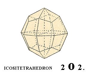
Figure 10. Yet another basic Form of the Cubic Hexakisoctahedral Crystal Class, the ikositetrahedron.
The Weiss symbol for this Form is accordingly :
(a : ma : ma), the Naumann symbol is mOm. and the Miller symbol is {hkk}.
In figure 10 we see this Form for (the case of) m = 2, which means that its symbols are respectively
(a : 2a : 2a), 2O2 and {211}.
In this way we can derive the rest of the Forms of this Crystal Class.
We can easily see that for the Isometric Crystal System, having three equivalent crystallographic axes, there are only seven types of basic faces possible, and from these we can derive the seven basic Forms of the Crystal System's most symmetrical Class, the Cubic Hexakisoctahedral Class, by subjecting a basic face to the symmetries of that Class.
We shall list the seven types of faces together with the Forms that can be generated from them:
- a : a : a (Octahedron)
- a : a : ma (Pyramid octahedron)
- a : a : ~a (Rhombic dodecahedron)
- a : ma : ma (Ikositetrahedron)
- a : ~a : ~a (Cube)
- a : ma : na (48-hedron, i.e. a polyhedron with 48 faces)
- a : ma : ~a (Pyramid cube)
We will expound and illustrate all this in more detail in the next Essay on The Isometric Crystal System.
The derivation of the shapes of the remaining Classes of the Isometric System will be dealt with later.
For The Crystal Classes of the other Crystal Systems other sets of crystallographic axes are used, in which not all axes are equivalent. To express this fact different symbols for their respective cut-off pieces are used, implying that we can have symbols like
a : a : mc, or a : ~b : mc.
The method, just described extensively, of indicating faces and Forms is, as has been said, developed by Chr. WEISS, and we can call it the method of Weiss.
The above derived Forms and their combinations all belong to the Cubic Hexakisoctahedral Crystal Class of the Isometric Crystal System (this Class served as an example of denotation and derivation of faces and Forms). It is the most symmetrical Class of this system, which means that the symmetry of regular grown crystals is the same as the empty building block (a cube) by which every crystal of this System can be thought to be constructed (by stacking those building blocks in an equivalent way along the three directions indicated by the crystallographic axes of the (Isometric) System).
What about the derivation of the shapes of crystals belonging to the less symmetrical Classes of this System? Well that is in principle very simple : We again start from the seven basic faces and subject each one of them to all the symmetries of the particular (lower symmetrical) Crystal Class. Because these remaining Crystal Classes (of the Isometric System) are all less symmetric than the Cubic Hexakisoctahedral Class, and because we can order these Classes according to a decreasing symmetry, we can generate the shapes of crystals of these less symmetrical Classes by starting, not with the basic faces, but with the basic Forms. We then eliminate more and more symmetries of those Forms, and will, in so doing, obtain Forms belonging to those lesser symmetrical Classes, together with their combinations.
This approach of deriving (conceptually) the Forms of the lesser symmetric Crystal Classes (of each Crystal System) uses the concepts of holohedric, hemihedric, hemimorphic, tetartohedric and ogdohedric. We shall expound this approach shortly.
But let us first expound a second method to denote (basic) Forms, developed by C. NAUMANN.
While the above expounded method (the method of Weiss) can denote faces as well as Forms, the method now to be discussed is only geared to symbolize Forms. But it is a very convenient one. So let us explain it.
In each of the six Crystal Systems that Form is chosen as (to be the) basic Form (of that System) of which each one of its faces cuts off finite pieces of each crystallographic axis (like in the Weissian method), and this basic Form is now denoted by the Naumannian symbol P (pyramid), with the exception of the basic Form of the Isometric System which is denoted by the symbol O (octahedron). The derivation coefficients used in the first method (the m, n and ~, in symbols like a : ma : ~a or like a : ~b : mc), will, when they relate to the Z-axis (the vertical crystallographic axis), be placed in front of the symbol P or O, and when they relate to the horizontal axes they will be placed after the symbol P or O.
So the derived pyramid (bipyramid) of Figure 4 (i.e. the larger bipyramid), denoted by the Weissian method as (a : b : 2c), will then be represented by the Naumannian symbol 2P, and a Form (a : b : ~c) will be denoted as ~P, etc. We already have used Naumannian symbols, namely in the Figures 9 and 10. In drawings we will, as we did in Figure 9, use the conventional symbol for infinity (a horizontal eight) instead of the symbol ~.
Further details of this very convenient method will be given in the ensuing Essays devoted to the different Crystal Systems and their Classes.
A third method (presently widely used) of symbolizing faces and Forms uses indices, the so called Miller indices.
Here each crystal face will be symbolized as follows : We take the reciprocal values of the Weissian coefficients for that face. Next these reciprocals are reduced to whole numbers (by multiplying them with an appropriate number -- which of course does not change their ratio). Finally the letters a, b and c and the :'s are omitted, and when a minus sign (-) is needed it will be placed above the relevant number. In the Essays of this website however we will use instead (because of typographical problems) an asterisk, *, placed after the relevant number to symbolize the fact that a negative part of a crystallographic axis is involved. The number relating to the X-axis (and its corresponding cut-off piece a) is the first number of the Millerian symbol, the number relating to the Y-axis (and its corresponding cut-off piece b) is the second number of that symbol, while the number relating to the Z-axis (and its corresponding cut-off piece c) is the third number of this symbol. Because the reciprocal value of infinity is zero, the number 0 will appear where in the Weissian symbol there was (a symbol for) infinity. The Miller indices representing a face will be enclosed between circular brackets ( ).
So the face a : b : c becomes (111), and the Miller indices of the face a : b : -c are (111*), and
a : b : ~c becomes (110). The Miller indices of the face a : b : 2c can be calculated as follows : the Weissian coefficients are 1, 1, 2. The reciprocal values of these are 1/1, 1/1, 1/2. We can bring these values to whole numbers by multiplying them by 2, resulting in the Millerian symbol (221). When the weissian coefficients are fractions then we must first reduce them to whole numbers. For instance 3a : 3/2b : c becomes 6a : 3b : 2c. The reciprocals of these are then 1/6, 1/3, 1/2. Multiplication by 6 gives 6/6, 6/3, 6/2, and thus the Millerian symbol (123). For the general Weissian symbol ma : nb : oc one writes (hkl) as the general Millerian symbol.
The whole Form is indicated in this method by placing the face symbol between braces { }. Thus the smaller bipyramid (a : b : c) of Figure 4 can be denoted by {111} as well as by the Naumannian symbol P.
The derivation of the Forms of the lower Symmetry Classes (of each Crystal System)
We will now expound some general concepts that are needed to (conceptually) derive all lower Symmetry Classes (Crystal Classes) of each Crystal System from its highest symmetrical Class (each Crystal System consists of several Crystal Classes -- Symmetry Classes -- one of which has the highest symmetry, i.e. it has the same symmetry as its empty building block).
Holohedric, hemihedric, hemimorphic, tetartohedric and ogdohedric.
It is possible to conceptually derive certain Forms from others by letting a part of the faces disappear in a systematic way. This can be accomplished by letting certain mirror planes disappear, resulting for each mirror plane in the supression of all the faces lying at one side of that plane, while letting the other faces extend in a corresponding way, i.e. letting them extend till they meet. In this way we obtain new Forms in which the relevant mirror planes are absent and which possess only a part of the faces of the original Forms. The orientation of these left-over faces is however the same as the corresponding ones in the original Form. Such new Forms are called merohedrons, while the original Forms are called holohedrons, and one distinguishes between hemihedrons, Tetartohedrons and ogdohedrons, in so far as the new Forms possess respectively half, a quarter or one eight of the faces of the original holohedric Forms.
Naturally two hemihedrons originate from a holohedron, four tetartohedrons and eight ogdohedrons , and one calls such Forms correlated Forms, i.e. the two hemihedrons originating from a holohedron are correlated Forms, so also the four tetartohedrons, and also the eight ogdohedrons. Most correlated Forms are congruent and are only distinguished by their orientation (with respect to the relevant crystallographic axes). But some relate to each other as being left- and right handed, implying that they cannot be transformed into each other by any mechanical operation like for instance a rotation. They are called enantiomorphous Forms.
There exist merohedrons which are not distinguished from their corresponding holohedrons by their outer shape, i.e. morphologically -- and that is always the case when the disappearing mirror planes were perpendicular to the faces of the holohedron. The fact that they possess a lower symmetry than the corresponding holohedrons -- and thus are merohedrons in a crystallographical sense -- is visible in their physical properties, and also by the fact that they can combine with other merohedrons. Where several types of mirror planes are involved, also several types of merohedrons can result, when either one set of mirror planes is suppressed or another set.
One signifies that type of hemihedron as (being) hemimorphous (hemimorphic) that originates when the one (for the crystal) unique (singular) mirror plane is suppressed, for example the equatorial symmetry plane of a tall or fat bipyramid. The effect of all this is that the axis that was perpendicular to that mirror plane has now become polar, implying that the crystal is differently developed at the two sides of that axis, in a geometrical as well as in a physical sense.
Remark : It should be noted that the concepts of holohedron, hemihedron, etc., and the derivation of the one from the other, and also the grouping of several Crystal Classes into Crystal Systems, is essentially just an aid to obtain a clear and convenient overview of the forms and shapes of crystals. In themselves the Crystal Classes (Symmetry Classes) are independent of each other and wholly equivalent.
In the next Essays we will apply this method of derivation of the lower Symmetry Classes from the highest one (the holohedric one) of the Crystal System concerned.
How the above concept of (basic) Form has its foundation in the crystal's internal structure
One might wonder why we can so easily speak of faces that together build up a Form, consisting of the same type of face, i.e. consisting of equivalent faces. Surely Crystals are the product of some "Lego" set of faces, that can be attached to each other. But no, crystals are not hollow structures, but 'filled' solids without container walls.In order to explain why the above 'constructions' are nevertheless conceptually possible and founded in real state of affairs, let us consider a certain fictitious two-dimensional crystal, consisting of two different sorts of constituents, say two different species of ions (= electrically charged atoms or groups thereof) with opposite electrical charge. Let us represent those ions by two kinds of disks, gray ones and red ones. Because like charges repel each other and opposite charges attract each other, each negatively charged ion wants to collect as many positive ions as its nearest neighbors as possible, and each positively charged ion wants to collect as many negative ions as its nearest neighbors as possibe. And every ion avoids a position next to any ion having a charge of the same sign.
The following crystalline structure will be the result of this (in this figure we depict only the internal structure and not its external boundaries, so we depict just an arbitrary fragment of the 'crystal') :
Figure 11. Internal structure of a two-dimensional ionic crystal (consisting of two different sorts of ions of opposite electrical charge).
This structure allows several kinds of flat faces to be developed. Each type of face presents a different atomic aspect to the growing environment (the nutrient environment). In the next figure we show that the structure under consideration allows three different types of faces, A, B and C, corresponding to three atomic aspects to the environment. The blue lines indicate these possible faces, and we must interpret the aspects as true aspects in so far as they are facing outwardly, i.e. towards the environment.
Figure 12. Examples of the three different kinds of faces allowed by the structure, according to the three different atomic aspects pictured below :
Figure 13. Three different atomic aspects of the structure of the figures 11 and 12.
When we look to aspect A we see that six faces are possible, i.e. six faces differing in orientatation but showing the same aspect to the growing environment. The nutrient material cannot distinguish among these six. When conditions in the environment are the same around the entire crystal, all six faces will grow at the same rate. And if they are the only faces appearing, then the 'ideal crystal' will have the shape of a regular hexagon, as shown in the next figure, and will not reveal the lower symmetry of the structure which has the symmetry of an equilateral triangle, not of a regular hexagon.
Figure 14. Regular hexagon bounded by A-faces only. This hexagon does not however possess the full symmetry of a regular hexagon. One set of mirror lines is suppressed, and the rotation axis is three-fold, not six-fold.
To show this clearly let us look to a (two-dimensional) structure which has the full symmetry of the hexagon :
Figure 15. A structure showing the full hexagonal (two-dimensional) symmetry.
This structure is that of a two-dimensional crystal consisting of only one atomic species. It has full hexagonal two-dimensional symmetry, namely a six-fold rotation axis and two sets of mirror lines (each set consisting of three equivalent mirror lines).
The structure of Figure 14 has a three-fold rotation axis instead of a six-fold one. It lacks one set of mirror lines, namely the red ones. Therefore this structure is analogous to a hemihedric Form from the domain of three-dimensional crystals. Such a (less dimensional) Form can only combine with (other such) Forms belonging to the same symmetry Class. So our hexagonal Form as depicted in Figure 14 can only combine with a triangular Form. Such a triangular Form could be bounded by three B-faces -- the B-faces alone, can only form triangles because only three of them (having different orientations) are possible in our structure (as depicted in the Figures 11 and 12), if indeed these three faces grow slowly enough to appear.
Figure 16. Triangular Form, possessing the full symmetry of an equilateral triangle. It has the same symmetry as the hexagon of Figure 14 and can therefore be combined with it.
The fact that faces that grow "slowly enough" will appear and remain, while fast growing faces disappear quickly, sounds a little paradoxical, but let me explain this, before we continue with the possible combinations of Forms.
The growth rate of a crystal face depends, in so far as only the crystal is concerned, on the atomic aspect the face has to the nutrient environment ( It can further depend on external influences, for example on the presence of certain chemicals -- impurities -- in that environment. A second factor determining the growth rate is the geometry of the lattice of the given crystal, see towards the end of Part XX of the Series on The Internal Structure of Crystals ). Now, the slower the face grows, the more likely it will survive, while relatively fast growing faces will ultimately disappear, as the next Figure illustrates :
Figure 17. Successive stages in growth of an imaginary two-dimensional crystal. Growing faster than the x-faces, the y-faces may finally disappear.
So when the A-faces (of the structure depicted in the Figures 11 and 12) appear, and the B-faces grow slowly enough for them also to appear, then the hexagon(al outline) will be mixed with a triangle, i.e. we get a combination of two Forms (both having the same symmetry) :
Figure 18. The combination of two Forms in a two-dimensional crystal. Here three corners of the hexagon are cut off by a triangle, and thus revealing the structure's true symmetry.
But it could also be that the B- and C-faces both grow very slowly relative to the growth rate of the A-faces. The latter will disappear. In this case we will get a combination of two triangles. And because the aspect to the nutrient environment is different in both cases (B-aspect and C-aspect, see Figure 13) the faces will almost certainly grow at a different rate, resulting in triangles of different sizes, and in this way again reflecting the lower symmetry of the structure, i.e. lower than the full symmetry of a regular hexagon. See the next Figure.
Figure 19. Combination of two unequally developed triangles in a two-dimensional crystal. The triangles cut off each others corners.
So for two-dimensional crystals we have now explained the growth of faces and the combinations of Forms. For three-dimensional crystals, i.e. for real crystals, the case is similar, and can thus finally be understood.
Let us give an example from real crystals showing a geometrical symmetry which is higher than the true symmetry, i.e. than the crystallographic symmetry :
The mineral Pyrite, FeS2, can be found in the form of a cube. But, often the faces of such a cube show growth stripes (striae) parallel to the edges of the cube (See Figure 20). Because of this the six secondary mirror planes of the highest symmetrical Class of the Isometric System (Cubic System) are suppressed. So the pyrite cube possesses a lower symmetry than a fully symmetrical cube like the ones of common salt, NaCl (in Nature occuring as the mineral Halite). A common salt cube possesses the full symmetry of a geometrical cube and it has an equal stripe pattern, generally expressing its cleavability. So in contradistinction to Halite, Pyrite belongs to a lower symmetry Class (of the same Crystal System).
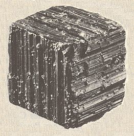
Figure 20. Partial suppression of the geometrical cube symmetry, because of absense of the secondary mirror planes, visible by the direction of striae in the mineral Pyrite.
The Stereographic Projection
There is a convenient method to display crystal faces (i.e. the orientation of faces) and symmetry elements (mirror planes, rotation axes) in a surveyable way on a two-dimensional surface. It is called the Stereographic Projection.The stereographic projection of a crystal is conceptually obtained in three steps, the last one of which is the actual stereographic projection.
1. The crystal is replaced by a set of face perpendiculars, by drawing perpendiculars originated from some point in the crystal to all the faces (or their extentions) of the crystal. This set of face perpendiculars is representative for the crystal, i.e. it represents all the angular relationships of its faces.
2. The set of face perpendiculars is replaced by a set of points on a sphere. This sphere is positioned such that the point from which the face perpendiculars originate becomes the center of that sphere. It is the projection sphere. Each face perpendicular intersects the (surface of the) sphere at a point (on that surface), the pole of the corresponding crystal face (face pole). In this way the set of face poles is an unequivocal representation of the crystal in so far it concerns the angles between the faces.
3. The set of points on the sphere is replaced by a coresponding set of points in a plane. There are several methods map a sphere on a plane. In Cartography one uses several such methods. If directions and angles are important -- as they are in crystals -- then the stereographic projection is the appropriate method.
The stereographic projection of points on the sphere can be obtained as follows :
Through the center (point) of the projection sphere a horizontal plane is introduced, the projection plane. This plane intersects the sphere according to a great circle, the primitive circle, it is the equator of the sphere. The line, going through the center of the sphere and perpendicular to the projection plane intersects the sphere in two oppositely lying points, N ("north pole") and S ("south pole"), N above and S below the projection plane.
In Figure 21 I have drawn a vertical section through the projection sphere, as described thus far. The sphere is then represented by a circle. The equatorial plane (plane of projection) is represented by the horizontal line passing through the center of that circle. The position of the crystal is indicated as well as the bundle of face perpendiculars. We can see where these -- when extended -- should intersect with the sphere. One such extended face perpendicular is drawn, namely the one that corresponds with face a of the crystal. Its point of intersection with the sphere is the point a', it is the face pole of face a.
Figure 21. Vertical section through the projection sphere, and stereographic projection ( a'') of a face a on the projection plane. The face pole is indicated by a'. Also the stereographic projection of another face of the crystal is indicated, its face pole is b' and by the stereographical projection it is projected onto itself. Its stereographic projection can be indicated by b'' and coincides with b'.
The projection of another face is also depicted, namely the face b. Because the figure depics a vertical section through the sphere, face a is inclined with respect to the projection plane (it makes an angle with it which lies between 0 and 90 degrees), while face b is vertically oriented with respect to the projection plane (it makes an angle of 90 degrees with it). From this we can see that all vertical faces will have their representations on the sphere precisely on the equatorial circle (primitive circle) of that sphere.
Let us now first take a look at the face pole of face a. It is a face pole lying on the nothern (i.e. upper) henisphere. This face pole (in order to project it stereographically) is now connected to the south pole, S which is the center of projection of points lying on the nothern hemisphere. The point of intersection, a'', of the connection line and the projection plane then is the stereographical projection of the face pole a' and consequently of the corresponding crystal face a.
If a pole lying on the southern hemisphere would be stereographically projected in the same way then the projection would end up outside the primitive circle, and further and further away when the face pole is nearer the south pole. To evade this one uses the north pole N as projection center for poles lying on the southern hemisphere. In this way the representations of all crystal faces fall within the confine of the primitive circle. To distinguish the projections of poles from the northern hemisphere from those of the southern hemisphere one indicates the former with a cross or a plus sign (+, or x) or just with a point (.), while the latter are indicated by little circle. When two stereographical projections, one from a pole above the equatorial plane and another from below, coincide on the plane of projection then one uses the sign for projections from the nothern hemisphere enclosed within a small circle.
Vertical crystal faces, like the face b in Figure 21, have their poles on the equator (primitive circle) of the sphere and are stereographically projected onto themselves, whatever projection point (N or S) is choosen.
Apart from crystal faces also symmetry elements can be stereographically projected in exactly the same way. Rotation axes can be extended and will intersect the surface of the sphere somewhere, and can then be stereographically projected on the plane of projection (the equatorial plane). A mirror plane can also be extended till it meets the surface of the sphere, and its pole will then be a circle on the surface of the sphere. This circle can then be stereographically projected onto the projection plane (by stereographically projecting every point of that circle). This will generally result in two arcs on the projection plane. These arcs enclose a diameter of the projection plane. Vertical circles on the sphere having their center in common with that of the sphere will finally end up as straight lines, namely as diameters of the primitive circle (equatorial circle).
Summarizing the projection of great circles (i.e. circles on the sphere, representing a pole of some plane (for instance a mirror plane), with their centers coinciding with that of the sphere) :
The stereographic projection of a vertical great circle is a straight line.
The stereographic projection of a horizontal great circle, which can only be the equator (primitive circle), i.e. the boundary the projection plane, is the equator itself.
The stereographic projection of an inclined great circle consists of two arcs spaning a diameter of the projection plane. An inclined great circle on the sphere (as pole of some inclined plane) has its one half on the nothern hemisphere and its other on the southern hemisphere. The northern part of the circle will be stereographically projected onto the projection plane through the south pole S as projection center, resulting in an arc spanning a diameter of the projection plane. The southern part of the circle will be projected through the north pole N as projection center, resulting in a second arc spanning the same diameter but now on the other side of it.
When we draw a stereographic projection of one or more features of a crystal -- its faces and/or its symmetry elements -- we always depict the projection plane (i.e. the equatorial plane of the sphere), and within it we draw the projections of the relevant features. The boundary (circumference) of the projection plane is generally represented by a circle outlined by a dashed line, unless the projection plane corresponds to the horizontal mirror plane of the crystal, if the latter has one. In that case the boundary will be represented by a solid line. A drawing as just described is called a stereogram (of the features concerned). See Figure 22.
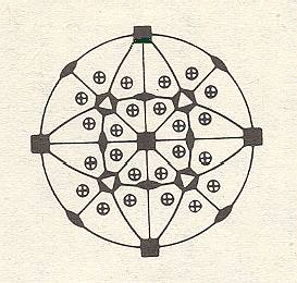
Figure 22. Stereogram of faces and symmetry elements of a crystal.
In the depicted stereogram of Figure 22 the faces are represented by encircled plus-signs, which means that in each case the projection of an upper face coincides with a projection of a lower face.
There is one horizontal mirror plane, which is represented in the stereogram by the solid boundary of the projection plane, visible as a circle.
There are four vertical mirror planes, represented in the stereogram by four solid diameters of the projection plane.
There are further four inclined mirror planes represented in the stereogram by four arcs spanning two diameters. In the present case each arc is the projection of the upper half of a great circle (representing a mirror plane) and at the same time the projection of the lower half of another great circle (representing another mirror plane).
Finally we see the stereographical projections of rotation axes. When we imagine a crystal within the projection sphere then we can extend the rotation axes till they intersect the spere. We thus obtain the poles of those axes. These poles are now stereographically projected in the same way as we did with face perpendiculars. They will then appear as locations on the projection plane. At each such location we will indicate, by means of certain conventional symbols, what type of rotation axis is represented in that location. In the figure we see the representation of two horizontally oriented 4-fold rptation axes (black squares at the perifery of the projection plane), one vertically oriented 4-fold rotation axis (black square in the center), two horizontally oriented 2-fold rotation axes (black ellipses at the perifery), four inclined 2-fold rotation axes (black ellipses inside the projection plane), and finally four inclined 3-fold roto-inversion axes (black hexagons with inscribed white triangles, inside the projection plane).
The stereographic projection is a very convenient way to depict crystallographic features on a two dimensional plane and allows a clear overview of those features, even when they are complicated as in Figure 22.
Overview of the 32 Symmetry Classes of Crystals
In this Overview we use the following abbreviations and terminology :
cs = center of symmetry.
p. = polar axis.
+ = present.
- = absent.
u [v] = u v-fold rotation axes present.
4* means a 4-fold roto-inversion axis.
An expression like "Hemimorphic of Holohedric" means that the hemimorphic Form is directly derived from the holohedric Form. The same applies to expressions like "hemimorphic of pyramidal hemihedric" which means that the hemimorphic Form is derived from a (in this case pyramidal) hemihedric Form (and consequently not from a holohedric Form).
one + one + one means three items present (for example three mirror planes) but belongong to three different types.
The Hermann-Maugin symbols are written down below each Class name.
(for example, three [4] = three 4-fold rotation axes present).
(for example, one [4*] = one 4-fold roto-inversion axis present).
The next six tables are going to list all the 32 Crystal Classes, one table for each Crystal System.
| Division | Class | mirror planes |
axes | cs |
| Holohedric | Hexakisoctahedric 4/m 3* 2/m |
3 + 6 | three [4] four [3] six [2] |
+ |
| Tetrahedric Hemihedric |
Hexakistetrahedric 4* 3 m |
6 | three [2] four [3] p. |
- |
| Pentagonal Hemihedric |
Duakisdodecahedric 2/m 3* |
3 | three [2] four [3] |
+ |
| Plagihedric Hemihedric |
Pentagonikositetrahedric 4 3 2 |
- | three [4] four [3] six [2] |
- |
| Tetartohedric | Tetrahedric pentagondodecahedric 2 3 |
- | three [2] four [3] p. |
- |
| Division | Class | mirror planes |
axes | cs |
| Holohedric | Ditetragonal-bipyramidal 4/m 2/m 2/m |
1 + (2 + 2) | one [4] two + two [2] |
+ |
| Hemimorphy of Holohedric |
Ditetragonal-pyramidal 4 m m |
2 + 2 | one [4] p. | - |
| Pyramidal Hemihedric |
Tetragonal-bipyramidal 4/m |
1 | one [4] | + |
| Hemimorphy of Pyramidal Hemihedric |
Tetragonal-pyramidal 4 |
- | one [4] p. | - |
| Trapezohedric Hemihedric |
Tetragonal-trapezohedric 4 2 2 |
- | one [4] two + two [2] |
- |
| Sphenoidic Hemihedric |
Tetragonal-scalenohedric 4* 2 m |
2 | one + two [2] | - |
| Sphenoidic Tetartohedric |
Tetragonal-bisphenoidic 4* |
- | one [4*] | - |
| Division | Class | mirror planes |
axes | cs |
| Holohedric | Dihexagonal-bipyramidal 6/m 2/m 2/m |
1 + (3 + 3) | one [6] three + three [2] |
+ |
| Hemimorphy of Holohedric |
Dihexagonal-pyramidal 6 m m |
3 + 3 | one [6] p. | - |
| Pyramidal Hemihedric |
Hexagonal-bipyramidal 6/m |
1 | one [6] | + |
| Hemimorphy of Pyramidal Hemihedric |
Hexagonal-pyramidal 6 |
- | one [6] p. | - |
| Trapezohedric Hemihedric |
Hexagonal-trapezohedric 6 2 2 |
- | one [6] three + three [2] |
- |
| Rhombohedric Hemihedric |
Ditrigonal-scalenohedric 3* 2/m |
3 | one [3] three [2] |
+ |
| Rhombohedric Tetartohedric |
Trigonal-rhombohedric 3* |
- | one [3] | + |
| Trigonal Hemihedric |
Ditrigonal-bipyramidal 6* m 2 |
1 + 3 | one [3] three [2] p. |
- |
| Hemimorphy of Trigonal Hemihedric |
Ditrigonal-pyramidal 3 m |
3 | one [3] p. | - |
| Trigonal Tetartohedric |
Trigonal-bipyramidal 6* |
1 | one [3] | - |
| Hemimorphy of Trigonal Tetartohedric (Ogdohedric) |
Trigonal-pyramidal 3 |
- | one [3] p. | - |
| Trapezohedric Tetartohedric |
Trigonal-trapezohedric 3 2 |
- | one [3] three [2] p. |
- |
| Division | Class | mirror planes |
axes | cs |
| Holohedric | Rhombic-bipyramidal 2/m 2/m 2/m |
1 + 1 + 1 | one + one + one [2] | + |
| Hemimorphy | Rhombic-pyramidal m m 2 |
1 + 1 | one [2] p. | - |
| Hemihedric | Rhombic-bisphenoidic 2 2 2 |
- | one + one + one [2] | - |
| Division | Class | mirror planes |
axes | cs |
| Holohedric | Prismatic 2/m |
1 | one [2] | + |
| Hemimorphy | Sphenoidic 2 |
- | one [2] p. | - |
| Hemihedric | Domatic m |
1 | - | - |
| Division | Class | mirror planes |
axes | cs |
| Holohedric | Pinacoidal 1* |
- | - | + |
| Hemihedric | Asymmetric 1 |
- | - | - |
In the next Essays we will treat of each Crystal System (and its Symmetry Classes) separately.
We shall begin with The Isometric System.