back to homepage
The External Shapes of periodic 2-D arrays of repeated two-dimensional motifs
Point symmetry and lattice structure determine the possible shapes that two-dimensional crystals can assume. In order to investigate these shapes we draw the relevant 2-D lattice, choose a suitable axial system (i.e. a set of crystallographic axes) to which the orientation of the crystal faces can be referred, determine the possible Forms (a Form is a set of equivalent faces), and consider possible combinations of Forms (belonging to the same Crystal Class (Point Group)). These combinations (and also single, but closed Forms) represent the possible shapes of the Crystals.
Oblique Net
The symmetry of its typical oblique building block (considered as empty) determines the 2-D Oblique Crystal System. It has two Classes, 2 and 1.
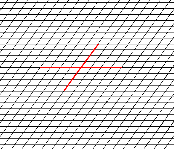
In Figure 1 a possible oblique net is drawn (notice that the drawing is not meant to be a perspectivic one. All angles are real angles).

Figure 1. A possible oblique net (2-D lattice). Two symmetry types of motifs can be periodically repeated according to this net. The possible symmetry types of the motifs are represented by the Point Groups 2 and 1. As indicated a set of crystallographic axes can be based on this net. See also Figure 2.
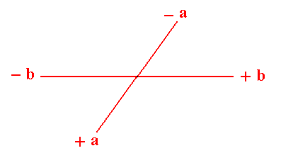
Figure 2. A chosen oblique axial system to describe faces and Forms.
(Of course in 2-D crystals the 'faces' are in fact just lines, but nevertheles we keep calling them faces). The a axis is not equivalent to the b axis.
Let us start with Point Group (= Crystal Class) 2.
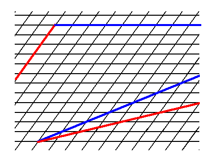
Figure 3. Some possible faces that cam be supported by the oblique net.
We insert a possible initial face -- in this case a face parallel to one of the crystallographic axes. See the next Figure.
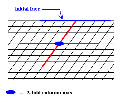
Figure 4. In order to construct one of the possible Forms of the Class 2 we introduce a face. This face will be multiplied by the 2-fold rotation axis perpendicular to the plane of the drawing (indicated by a small solid blue ellipse) such that the resulting face configuration (Form) will have point symmetry 2. The next Figure illustrates the action of the 2-fold rotation axis resulting in an open Form consisting of two parallel faces.
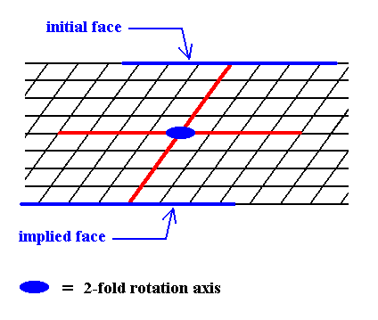
Figure 5. When a face is introduced, such that it is parallel to one of the crystallographic axes, a second face, parallel to the initial one is implied. The result is an open Form, possessing indeed the point symmetry of the present Class (2). As such it cannot (because it is open) constitute a (2-D) crystal. Only when it combines with other Forms of the same Crystal Class, such that a closed face configuration is the result, can it go into the constitution of a crystal.
So we've for the first time constructed a Form of Class 2 of the 2-D Oblique Crystal System. It is a special Form because the orientation of the initial face is special, the face is parallel to one of the crystallographic axes, which themselves are parallel to the two directions of translation.
Another special Form can be derived from an initial face parallel to the other crystallographic axis. See Figures 6 and 7.
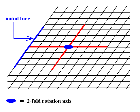
Figure 6. Introduction of a face, parallel to the other of the crystallographic axes.
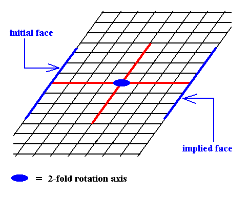
Figure 7. The presence of an initial face, as indicated in Figure 6, implies a second face parallel to the intial face, because of the action of the 2-fold rotation axis. The resulting face pair is again a special Form.
We can also introduce a face with a more general orientation with respect to the crystallographic axes (Recall that these axes are not equivalent). See Figure 8.
Figure 8. Introduction of a face with a more general orientation to the crystallographic axes implies -- because of the action of the 2-fold rotation axis -- a second face parallel to the initial one. The resulting face pair is an open, general Form.
Other more general orientations of introduced faces are possible. The next Figure depicts one such face, together with a second face implied by it.
Figure 9. Introduction of a face with a more general orientation with respect to the crystallographic axes implies a second face parallel to the initial one. The resulting face pair is yet another open, general Form.
These Forms (each of which is a set of equivalent faces) can (and in the present case should) enter in combinations with each other. The point symmetry of the resulting face configuration is conserved as long as all the Forms participating in a combination belong to the same Crystal Class (Point Group). Figure 10. depicts such a combination. The resulting face combination turns out to be closed, so it can indeed represent a genuine (2-D) crystal.
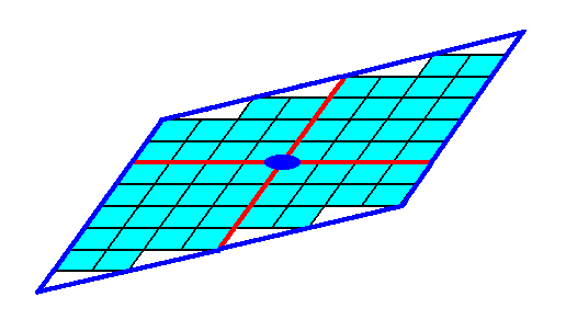
Figure 10. A combination of the Forms of Figures 7 and 9. Because this combination is closed it can represent a (2-D) crystal. The red lines signify the two crystallographic axes, while the small blue solid ellipse signifies a 2-fold rotation axis, as the only point symmetry element of the crystal.
Of course the building blocks are imagined to be utterly small, resulting in the faces always to be smooth macroscopically.
The next Figure shows the same 2-D crystal, without indication of crystallographic axes and the 2-fold rotation axis. The crystal shape emerges from a combination of two Forms : one Form consisting of the two faces d, the other Form consisting of the faces e.
Figure 11. Two-dimensional crystal.
Heavy solid blue lines indicate faces.
Figure 12 shows the same crystal without the auxiliary lines indicating faces. The nodes of the lattice are at the intersections of the lines outlining the building blocks. These nodes indicate the periodic repetition of motifs, and are equivalent.
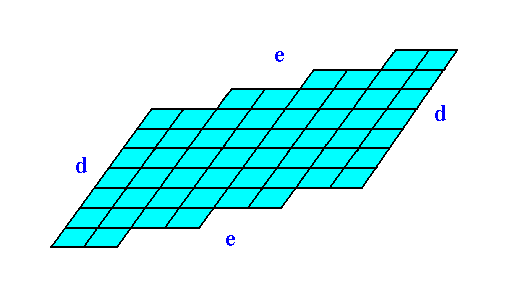
Figure 12. The two-dimensional crystal, drawn without any auxiliary features.
The faces d are associated with a higher density of nodes than the faces e are. When everything else would be the same, the faces d would grow slower than the faces e, because more material (forming the motifs) must be imported from the growing environment.
Figures 11 and 12 show that if the faces d were chemically and physically like the faces e they would then grow slower than the faces e because more nutrient material must be imported from the growing environment to complete a layer of motifs on the (growing) crystal.
The next two Figures give two more possible Forms.
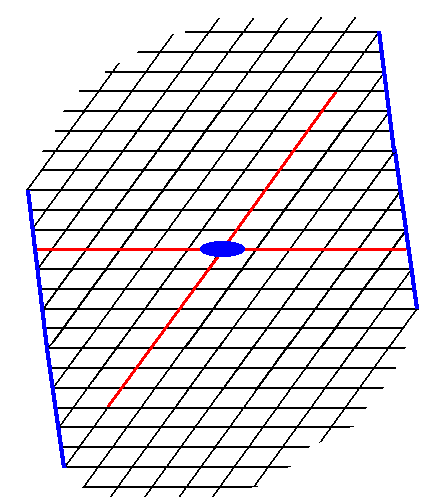
Figure 13. A possible Form of the 2-D Crystal Class 2 of the 2-D Oblique Crystal System. The axial system, and the 2-fold rotation axis representing the point symmetry of the Form, are indicated.
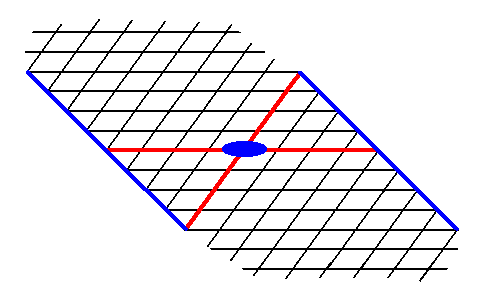
Figure 14. A possible Form of the 2-D Crystal Class 2 of the 2-D Oblique Crystal System. The axial system, and the 2-fold rotation axis representing the point symmetry of the Form, are indicated.
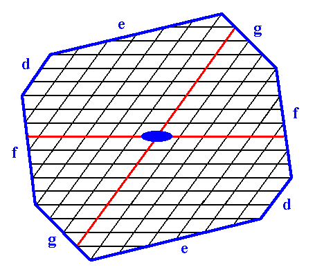
Figure 15. Construction of a 2-D crystal from a combination of four Forms :
First Form : The two faces d, i.e. the Form of Figure 7.
Second Form : The two faces e, i.e. the Form of Figure 9.
Third Form : The two faces f, i.e. the Form of Figure 13.
Fourth Form : The two faces g, i.e. the Form of Figure 14.
The axial system, and the 2-fold rotation axis representing the point symmetry of the crystal, are indicated. The final result of the construction is given in the next Figure.
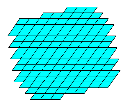
Figure 16. A two-dimensional crystal constructed from the four Forms mentioned above.
The final habit of the crystal, i.e. its intrinsic shape, is determined by several factors :
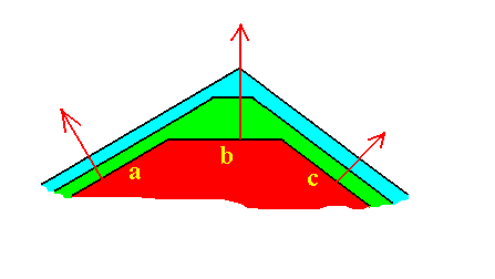
Figure 17. The face b is the fastest growing face, but just because of that it grows itself out of existence.
The next Figure depicts yet another possible combination of Forms : the combination of the Form from Figure 5 with the Form from Figure 7.
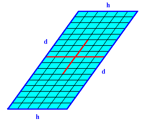
Figure 18. A 2-D crystal of the Class 2 from a combination of two Forms.
The faces h cut through less lattice nodes than the faces d do. So when other conditions do not interfere the faces h grow faster than the faces d. And because the latter faces are parallel to each other the faces h do not grow out of existence.
This implies that the crystal becomes elongate in the direction along the faces d.
Different faces of a crystal, grown from a solution or melt of a certain chemical substance, often show different aspects of the chemical composition to the growing environment. When, for example, we have an ionic crystal, i.e. a crystal composed of electrically charged atoms or groups of atoms, some faces could be such that they are the result of the stacking of electrically charged atomic layers : On top of a layer wholly consisting of, say, negative ions, a second layer is deposited, wholly consisting of positive ions. An on this layer a third layer will be deposited, wholly consisting of negative ions, and so on. It is evident that such faces will grow very fast, because the nutrient material is actively drawn to the crystal surface and deposited on such a face. On the contrary another face of that same ionic crystal could be such that it -- because of its different orientation in the crystal -- is the result of the stacking of electrically neutral (atomic) layers, neutral, because each layer consists of as many negative as positive ions. Such layers will not actively attract new material from the nutrient environment. Deposition only takes place when particles (ions) happen to be at the right (deposition) site.
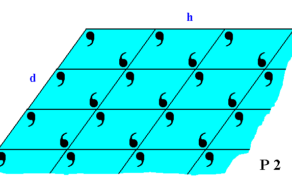
Figure 19. The faces d and h of Figure 18, with the building blocks furnished with motif units. The motifs associated with the lattice nodes -- recall that these nodes are just theoretical constructs to indicate the periodic repetition of the motifs -- have a point symmetry 2, and the lattice is an oblique net, so the Plane Group is P2. We can see that the motifs at the faces (d and h) are incomplete, reflecting the fact that generally the chemical valences are unsatisfied or distorted at the faces (i.e. at the surface of the crystal). This condition implies a higher (surface) energy than at places where the valences are satisfied. Consistent with the principles of Thermodynamics Nature tries to restore this energetical imbalance by striving to reduce the surface energy. This is accomplished by the deposition of a new layer of material. The valences are now satisfied and the old layer has reduced its surface energy, but now the new layer has an excess of surface energy, so to satisfy its valences and thus reducing its surface energy, a new layer should be added, and so on.
If we consider the visible part of the structure of Figure 19 as a whole crystal, then we have four faces. Every two such faces that are parallel to each other are equivalent, they present the same atomic aspect to the growing environment of the crystal. See Figure 19a.
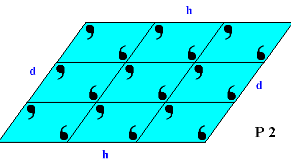
Figure 19a. This 2-D crystal has four faces, d, d, h, h.
The faces d, d are not only parallel to each other, they are also equivalent, as can be seen by them presenting identical atomic aspects to the growing environment of the crystal. The same goes for the faces h, h.
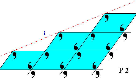
Figure 20. The face ( i ), seen in Figure 8, is here again depicted, with the building blocks furnished with motif units. The lattice is still according to the oblique net, and the motifs associated with the nodes again have point symmetry 2. But also here the motifs are incomplete at the face of the crystal.
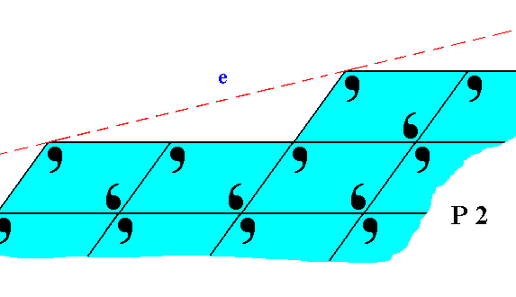
Figure 21. The face e of Figure 11, with building blocks furnished with motif units and as such representing Plane Group P2. Also here the motifs are incomplete at the crystal's surface.
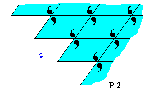
Figure 22. The face g of Figure 14 and 15, with building blocks furnished with motif units and as such representing Plane Group P2. Also here the motifs are incomplete at the crystal's surface, which is in the present case only evident when we consider the motif s.l.
The Figures 19, 20, 21 and 22 clearly show that different faces can display different atomic aspects to the growing environment (where the motifs stand for chemical configurations). And this can make a difference in their respective growth rates, determining the intrinsic shape of the crystal.
In the next Part we will discuss the 2-D Crystal Class 1 (of the 2-D Oblique Crystal System, also based on the Oblique Net) which -- like the Class 2 -- has only one Plane Group, in this case the Plane Group P1.
To continue, click HERE for Part Nine.
back to homepage