Continuing the investigation of Part Four, we're now going to derive all the Crystal Classes having more than one more-than-2-fold rotation axis.
The number of possible combinations of symmetry elements within this group of Classes, and so the number of possible Crystal Classes, is very limited, because when the higher-fold axes are going to multiply each other, this generally becomes a run-away process, proceeding until infinity, resulting in total isotropy. The latter means that the number of axes has become infinite. There are no special directions left. The result then consists of spheres or rotation bodies (like ellipsoids). We get axes having infinite-foldness, forbidden in crystals.
So only certain combinations of axes, making certain definite angles with each other, are possible, in which the foldness of the axes is finite. One such combination in which the foldness is finite is the following :
Six 5-fold axes, ten 3-fold axes and fifteen 2-fold axes. But this combination cannot occur in crystals because 5-fold axes are impossible there. This combination of axes is realized in two geometrical objects, the regular dodecahedron and the regular icosahedron.
It can be mathematically proved that only two combinations of axes (within this group) are possible for crystals :
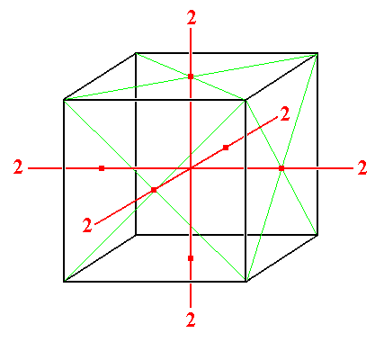
1. Four 3-fold rotation axes making angles with each other of 1090 28' (or 700 32'), always combined with three 2-fold rotation axes along the bisectors of these angles. See Figure 1.
Figure 1.
First combination of axes (containing more than one more-than-2-fold axis) allowed in crystals. It fits into a cubic framework.
In this drawing we can visualize the four 3-fold rotation axes going from one corner of the cube to the very opposite corner (for reasons of clarity they are not actually drawn). Further we can see the three 2-fold rotation axes connecting the centers of opposite sides.
The foldness of the axes is indicated by a numeral.
2. Four 3-fold rotation axes making angles with each other of 1090 28' (or 700 32'), always combined with three 4-fold rotation axes making angles with each other of 900 and six 2-fold rotation axes. See Figure 2.
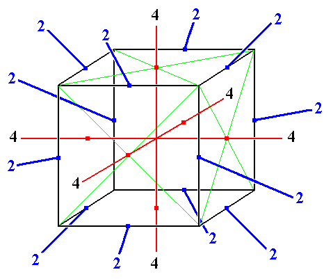
Figure 2.
Second combination of axes (containing more than one more-than-2-fold axis) allowed in crystals. It fits into a cubic framework.
In this drawing again the four 3-fold rotation axes, connecting opposite corners of the cube, are not drawn but are nonetheless present. Further we see the three 4-fold rotation axes connecting opposite sides of the cube. We see also the six 2-fold rotation axes connecting opposite edges of the cube.
The foldness of the axes is indicated by numerals.
The next Figure shows (the construction of) one of the planes which contains two of the four 3-fold axes. We can see that they are not perpendicular to each other.
Their obtuse angle is 1090 28'.
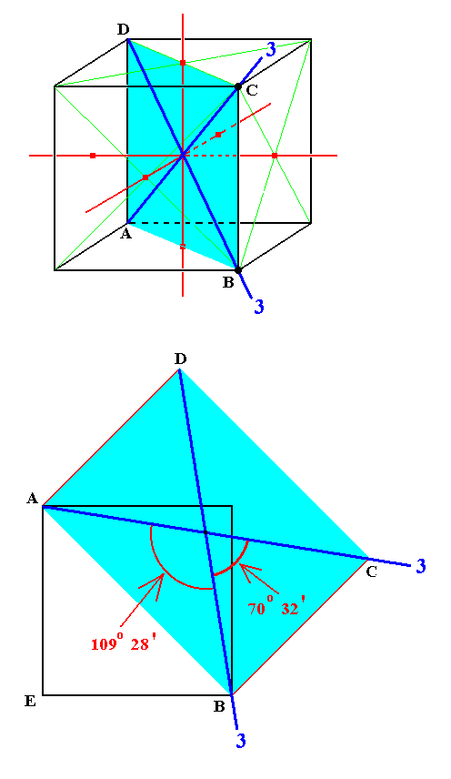
Figure 2a. In the top (perspectivic) image we see the cubic framework consistent with the two basic axial combinations. Two (out of a total of four) 3-fold axes are drawn. They lie in the plane ABCD.
This plane is constructed in the lower (non-perspectivic) image. Note that here we have to do with a planar construction, i.e. EABCD is one flat plane. AE = EB = AD is equal to any edge of the cube, and AB is equal to the diagonal of any face of the cube. In the constructed plane we have again drawn the two 3-fold axes which it contains.
The angles between these 3-fold axes are indicated.
The next Figure depicts the four 3-fold axes present in both basic axial combinations.
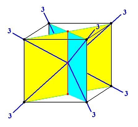
Figure 2b. The four 3-fold axes figuring in both allowed axial configurations (1 and 2).
These two basic axial combinations together comprise the the set of allowed locations of axes within any combination in which there is more than one more-than-2-fold axis.
From these two basic combinations of symmetry elements, other combinations, belonging to the group under discussion, can be derived by adding symmetry elements.
When we do so we should not cause the implication of other axes at other locations than those specified in the two basic axial combinations taken together. In fact all these allowed axial directions are already given in group 2.
In the derivation of the 27 Crystal Classes having at most one more-than-2-fold axis (Part I, II, III and IV), we added symmetry elements that did not multiply the vertical n-fold axis. They were :
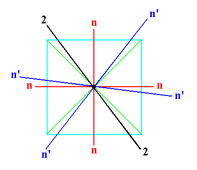 |
Figure 2c. The addition of a 2-fold rotation axis (black) such that it does not make angles of 900 or 450 with existing n-fold axes, n (red), multiplies these axes, generating the axes n' (blue). One of the effects is that also the 3-fold axes will be multiplied. |
Also an added mirror plane should not make angles different from 900 or 450 with the n-fold axes. Addition of a mirror plane perpendicular to an n-fold axis (and then consequently parallel to the other two), does not multiply those n-fold axes (and by consequence the 3-fold axes), because those axes are then mapped onto themselves (See Figure 3). If a mirror plane is added such that it contains just one n-fold axis it will not multiply the n-fold axes provided it makes an angle of 450 with the other two n-fold axes (See Figure 3a).
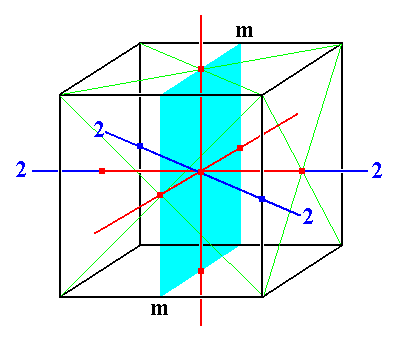
Figure 3.
All existing more-than-2-fold axes will not be multiplied when a center of symmetry is added, because it maps those axes just onto themselves.
The three n-fold axes (red) will not be multiplied by the addition of a 2-fold rotation axis if such an axis either coincides with one of the n-fold axes, or makes an angle of 450 with two of them. The n-fold axes will simply be mapped onto themselves by such a 2-fold axis.
Addition of a mirror plane will not multiply the n-fold axes, if it contains two of those n-fold axes. The three n-fold axes will simply be mapped onto themselves by such a mirror plane.
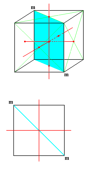 |
Figure 3a.
Top : A 3-dimensional view of a mirror plane containing one n-fold axis and making angles of 450 with the other two.
|
As in the case of a 2-fold axis, an added mirror plane not making an angle of 900 or 450 with one or another n-fold axis multiplies the n-fold axes. See Figure 3b.
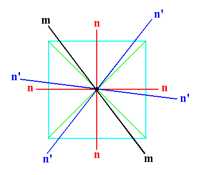 |
Figure 3b. The addition of a mirror plane m (black) such that it does not make angles of 900 or 450 with existing n-fold axes, n (red), multiplies these axes, generating the axes n' (blue). One of the effects is that also the 3-fold axes will be multiplied. |
The enumerated symmetry elements must be such that they do not generate axes at locations other than those of group 1 and 2, i.e. they not only should not multiply the n-fold axes (which they do not under the above mentioned conditions), they also should not multiply the other axes occurring in the two allowed basic axial configurations.
Center of symmetry
Addition of a center of symmetry will not create new axes in other directions than those present in the two basic axial configurations (1 and 2). This is so because a center of symmetry is a point and so, when added, cannot impose new directions within the structure. See Figure 4.
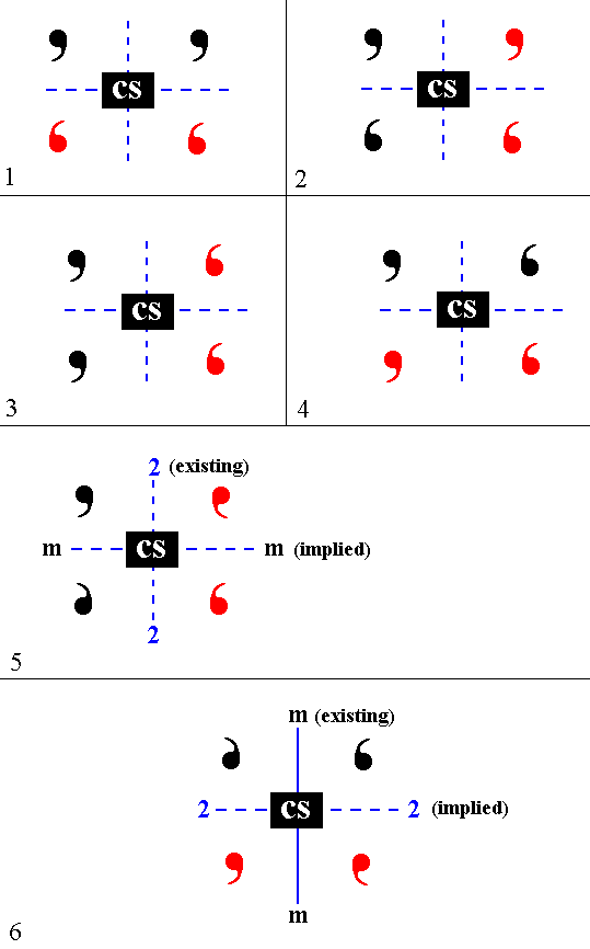
Figure 4. (Addition of) a center of symmetry does not impose a direction on a motif pattern.
The motifs in this Figure are supposed to be 3-dimensional and asymmetric, expressed by their shape and color. We can imagine that the color red indicates the motif's other side turned to the beholder. A 2-fold rotation axis is indicated by the symbol 2, and a mirror plane by m. A center of symmetry is indicated by the symbol CS.
Each part of this Figure, I mean the parts 1, 2, 3, 4, 5 and 6, gives two initially existing motifs (in the upper half of each drawing). The two other motifs (in the lower half of each drawing) are generated as a result of the addition of a center of symmetry. In all the cases depicted no new directions are created.
In (5) we have the following situation : The two initial motifs are related to each other by a 2-fold rotation axis. When a center of symmetry is added a mirror plane, perpendicular to the existing 2-fold axis, is implied. No new direction is created because a mirror plane is always equivalent to a 2-fold roto-inversion axis perpendicular to it. So the only definite direction associated with this implied mirror plane is an axis perpendicular to it. But this direction was already present in the form of the existing 2-fold rotation axis.
In (6) we have two initial motifs related to each other by a mirror plane. When a center of symmetry is added a 2-fold rotation axis is implied. Also this implied axis does not represent a newly created direction, because the mirror plane, initially present, is equivalent to a 2-fold roto-inversion axis perpendicular to it and thus coinciding with the implied 2-fold rotation axis.
2-fold rotation axes
As has been said, addition of a 2-fold rotation axis must be such that no new axial directions are created. So in the basic axial combination 2 no axes can be added, while in the basic combination 1 2-fold axes can be added at certain locations where there are no such axes present but only when there is an axis present in the corresponding location in the basic combination 2. Indeed we have shown above that adding 2-fold axes at other locations (directions) cause multiplication of the more-than-2-fold axes.
Mirror planes
In the two basic groups (1 and 2) of possible axial directions (and also positions) for Classes having more than one more-than-2-fold axis the occurring foldnesses are 2, 3 and 4. The 3-fold axes here make angles of 1090 28' (and 700 32') with each other.
The 2-fold axes situated between the 3-fold axes and connecting the midpoints opposite edges of the cube (see Figure 2) two by two make angles of 900 between each other. Around each 4-fold axis they are arranged according to a 4-fold symmetry. The other possible 2-fold axes, replacing the 4-fold axes (as in the basic axial combination 1) are perpendicular to each other. Here they represent the n-fold axes imposing a 2-fold symmetry on the structure, when viewed along one (or another) of these axes.
The vertical axis -- which is equivalent to two other horizontal axes perpendicular to it -- either is 2-fold or 4-fold (The 4-fold axis may come (in combinations yet to be derived) in two varieties, namely a 4-fold rotation axis and a 4-fold roto-inversion axis. The latter is an independent symmetry element). So there 3-fold and 6-fold axes cannot occur, i.e. axes connecting the centers of opposite faces of the cube cannot be 3- or 6-fold.
Thus, parallel to such an axis only mirror planes can be added that make angles of 450 or 900 with existing axes perpendicular to it, conserving in this way the 2- or 4-foldness of that axis.
If we have a vertical mirror plane such that it contains a 2-fold axis, which lies between the 3-fold axes and connects two opposite edges of the cube, then a mirror plane, perpendicular to the first mirror plane, is implied. Such mirror planes, which are diagonally inclined, appear as arcs in stereograms. This is because the intersection of such a plane with the projection sphere is an inclined circle. The upper half of this circle is now projected (with the south pole of the projection sphere as projection center) onto the projection plane (= the equatorial plane of the projection sphere) resulting in an arc. The implied mirror plane does not create a new direction, because the direction associated with that mirror plane -- namely a direction perpendicular to that mirror plane -- is already present in the form of (another) 2-fold axis (present in the second group of basic axial directions). See Figure 5.
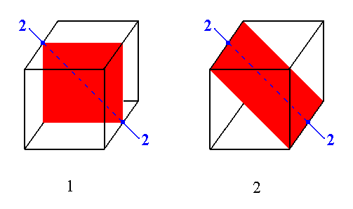
Figure 5.
(1). Vertical mirror plane (seen as a straight line in stereograms) containing a 2-fold rotation axis.
(2). Implied diagonally inclined mirror plane (seen as an arc in stereograms) containing the 2-fold rotation axis.
The two mirror planes are perpendicular to each other.
All these mirror planes, horizontal, vertical (such that 2-fold or 4-fold symmetry is conserved) and diagonally inclined, when added, do not generate new directions (axes) in other locations than those (specified) in the two basic groups (1 and 2) of possible axial directions.
We now have prepared ourselves for the derivation of the remaining Crystal Classes (i.e. the Classes beyond the 27 Classes already derived in the previous Parts). They belong to the group of symmetry combinations having more than one more-than-2-fold rotation axis.
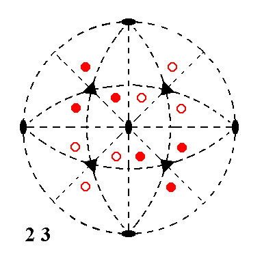
Figure 6. Stereogram of the symmetry elements of the Class 23, and of the face poles of its most general Form.
2-fold rotation axes are indicated by small solid ellipses.
3-fold rotation axes are indicated by small solid triangles.
The projections of upper face poles are indicated by small red solid circles, while those of lower face poles are indicated by small red open circles.
This symmetry configuration does not have mirror planes, as is indicated by the dashing of (lines representing) possible mirror planes (i.e. possible in other classes). It is the symmetry of the first basic axial combination (1).
Figure 6a. The Tetrahedric Pentagondodecahedron as the general Form of the Class 23.
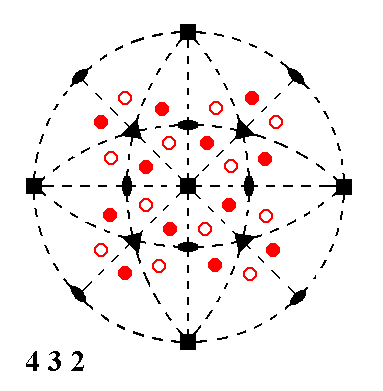
Figure 7. Stereogram of the symmetry elements of the Class 432, and of the face poles of its most general Form.
4-fold rotation axes are indicated by small solid squares.
Also this Class does not possess mirror planes. It has the symmetry of the second basic axial combination (2).
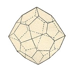
Figure 7a. The Gyroid (or Pentagonicositetrahedron) as the general Form of the Class 432.
To the symmetry content of these two Classes we're now going to add the above mentioned symmetry elements, one at a time, under the above determined conditions, in order to derive further Classes.
Addition of a center of symmetry to the symmetry content of Class 23 yields Class 2/m 3* (in which 3* signifies a 3-fold roto-inversion axis -- in the literature the * is written as a score above the numeral preceding it, in our case the numeral 3). See Figure 8.
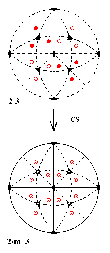 |
Figure 8.
Derivation of Class 2/m 3* from Class 2 3 by adding a center of symmetry. |
Addition of a center of symmetry to the symmetry content of Class 432 yields Class 4/m 3* 2/m. See Figure 9.
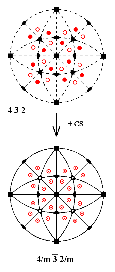 |
Figure 9.
Derivation of Class |
In the above derivation addition of a center of symmetry implies mirror planes perpendicular to existing 2-fold axes. Four of those axes are inclined axes. We see them in the central part, between the 3-fold axes, in the stereogram of Class 432. These inclined axes also get their mirror planes perpendicular to them. Each of these implied mirror planes is an inclined mirror plane and appears in the stereogram of Class 4/m 3* 2/m as a continuous arc opposite to the corresponding inclined 2-fold axis.
(Recall that in a stereogram a crystal face is represented by the projection (onto the projection plane) of the piercing point (through the projection sphere) of the face's perpendicular. An axis is represented by the projection (onto the projection plane) of its piercing points (through the projection sphere). But a mirror plane is represented by the projection (onto the projection plane) of its intersection (which is a circle) with the projection sphere. When a mirror plane is vertical or inclined, we take the upper part of its intersection with the projection sphere and project that part onto the projection plane, resulting respectively in a continuous straight line or a continuous arc. When a mirror plane is horizontal, its intersection with the projection sphere coincides with the equator of the projection sphere. The projection onto the projection plane of this equator coincides with the equator itself, resulting in a continuous circle outlining the projection plane.)
Two such inclined 2-fold axes and the corresponding inclined mirror planes are depicted in Figure 9a.
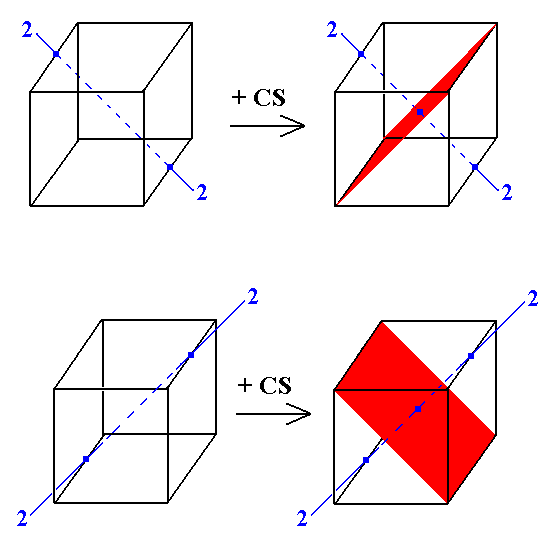
Figure 9a. Addition of a center of symmetry implies mirror planes perpendicular to existing 2-fold axes.
Addition of a 2-fold rotation axis can only be such that it will end up precisely between two existing axes, in order to comply with the allowed axial directions (The total of these allowed directions is seen in the basic axial combination 2, i.e. that of Class 432).
In fact there are two types of possible 2-fold rotation axes :
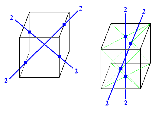
Figure 9b.
Left : Two instances of a diagonal 2-fold rotation axis.
Right : Two instances of a non-diagonal 2-fold rotation axis.
Class 23 already possesses all possible non-diagonal axes.
Class 432 possesses all possible non-diagonal 4-fold rotation axes, and those axes necessarily also have 2-fold symmetry ( They repeat an image every 900, so also every 1800).
Class 2/m 3* already possesses all possible non-diagonal 2-fold axes.
Class 4/m 3* 2/m also already possesses all possible non-diagonal 2-fold rotational symmetry, contained in its non-diagonal 4-fold rotation axes.
So for the time being we only have to investigate the addition of a diagonal 2-fold rotation axis.
Addition of a diagonal 2-fold rotation axis to the symmetry content of Class 23 yields Class 432.
Figure 10. Stereographic projection of the symmetry elements of Class 23, and of the face poles of its most general Form.
In the next Figure we're going to add a diagonal 2-fold rotation axis and see what happens as a consequence.
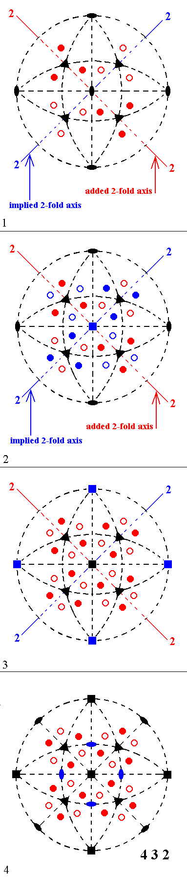 |
Figure 11. Derivation of Class 432 from Class 23 by adding a diagonal 2-fold rotation axis.
(1). Addition of a diagonal 2-fold rotation axis to the symmetry content of Class 23. Existing horizontal 2-fold axes generate yet another 2-fold axis.
|
In (2) of the above Figure we stated that because of the action of the new 2-fold axes (one added, one implied) the already existing vertical 2-fold axis becomes a 4-fold axis. We concluded this on the basis of the emerging new pattern of motifs (represented by face poles).
The next two Figures show -- the second one by means of real motifs -- that such a conclusion is indeed correct.
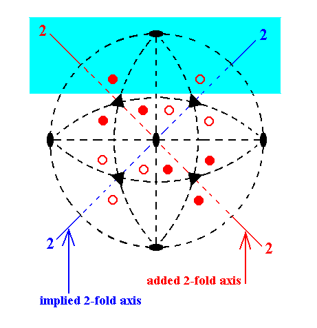
Figure 11a. Stereogram of Class 23
The next Figure deals -- in terms of real motifs -- with the elements in the shaded area of the stereogram.
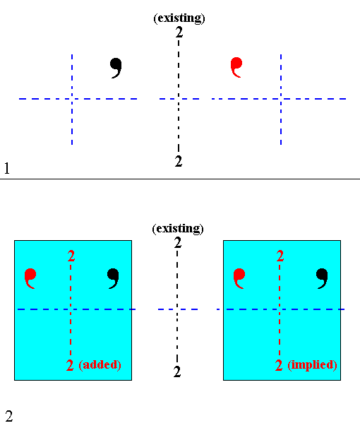
Figure 11b. Implication of 4-fold rotational symmetry about the vertical axis, as a result of the addition of a horizontal 2-fold rotation axis to the symmetry content of Class 23.
(1). Two motifs, an upper one (black) and a lower one (red), related to each other by an existing 2-fold rotation axis.
(2). Addition of a 2-fold rotation axis, and the implication of yet another one, create two units (each consisting of two motifs) which are exact repetitions of each other (For reasons of clarity the added and implied axes are drawn parallel to the existing 2-fold axis. In reality they make angles of 450 with it). This shows that the whole upper left unit in (2) of Figure 11, consisting of six motifs, is repeated after a rotation of it by 900 about the vertical axis in the center of the stereogram. The same applies to the other three units, which effects that the four units (of (2) of Figure 11) are mapped onto each other every 900 rotation about the vertical axis. This means that this (vertical) axis has become a 4-fold rotation axis.
In (3) of Figure 11 we stated that the existing 3-fold axes multiply the 4-fold axis, resulting in three such axes perpendicular to each other (and replacing initially existing 2-fold axes).
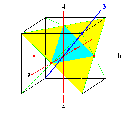
Figure 11c. The 3-fold axis maps the 4-fold axis onto axis a and onto axis b (which were originally 2-fold axes), turning them into 4-fold axes.
Addition of a 2-fold rotation axis to Class 432 is not possible because all the allowed locations for axes are already occupied in the symmetry configuration of this Class.
Addition of a diagonal 2-fold rotation axis to the symmetry content of Class 2/m 3* yields Class 4/m 3* 2/m. Let us first depict the stereogram of Class 2/m 3*.
 |
Figure 12. Stereographic projection of the symmetry elements of Class 2/m 3* and of the face poles of its most general Form. The 3-fold roto-inversion axes (3*) are indicated by small black open triangles. Upper and lower face poles coincide on the projection plane, and are as such indicated by small red centered circles. |
The next Figure shows the derivation of Class 4/m 3* 2/m. This Class was already derived earlier, so nothing new is actually generated.
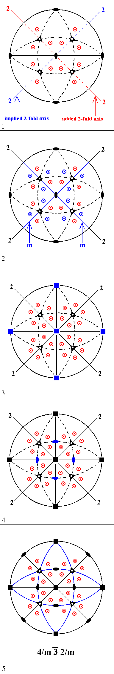 |
Figure 13. Derivation of Class 4/m 3* 2/m from Class 2/m 3* by adding a diagonal 2-fold rotation axis.
(1). Addition of a diagonal 2-fold rotation axis to the symmetry content of Class 2/m 3*. Existing horizontal 2-fold axes generate yet another 2-fold axis.
|
The next Figure explains what is stated in (5) of the above Figure.
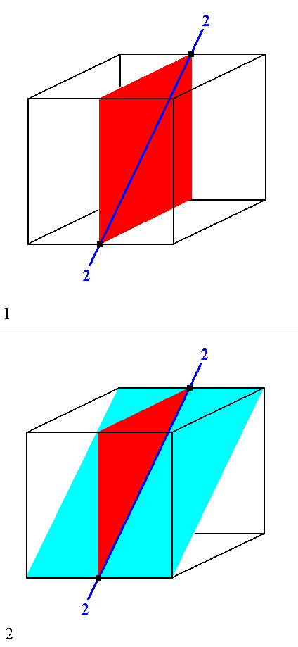
Figure 14. In (1) of this Figure we see a vertical mirror plane containing an inclined 2-fold rotation axis. In fact it is just a mirror plane containing a 2-fold rotation axis, and we know that this implies a second mirror plane perpendicular to the first one. Here this means that an inclined mirror plane is implied (2).
Addition of a 2-fold axis to the Class 4/m 3* 2/m is not permissible because in this Class all the allowed positions are already occupied with axes.
Until now we have (derived) the following Classes (belonging to the group the members of which possess more than one more-than-2-fold axis) :
When we're going to add mirror planes to the symmetry content of the two initial Classes and to that of already derived Classes, the following two types of mirror planes
must be considered :
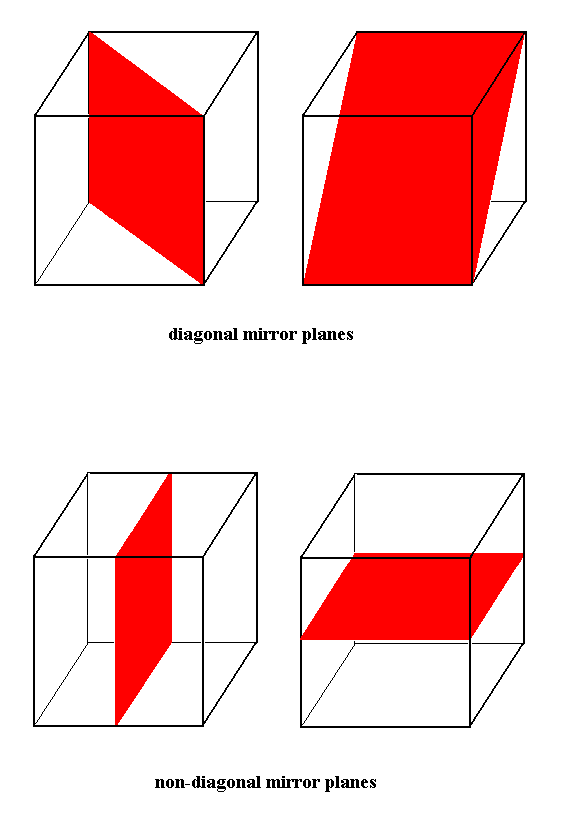
Figure 15.
Diagonal mirror planes. Six such planes can occur.
Non-diagonal mirror planes. Three such planes can occur.
Addition of a non-inclined vertical diagonal mirror plane to the symmetry content of the Class 23 yields Class 4* 3m. See Figure 16.
 |
Figure 16. Derivation of Class 4* 3m from Class 23 by adding a non-inclined vertical diagonal mirror plane.
(1). Stereographic projection of the symmetry elements of the Class 23, and of the face poles of its most general Form.
|
In (4) of the above Figure we stated that " The new motif configuration has 4-fold roto-inversion symmetry with respect to the vertical axis, so this axis, which originally was a 2-fold axis, becomes a 4-fold roto-inversion axis (indicated by a small blue open square in the center of the stereogram)."
The next Figure explains this.
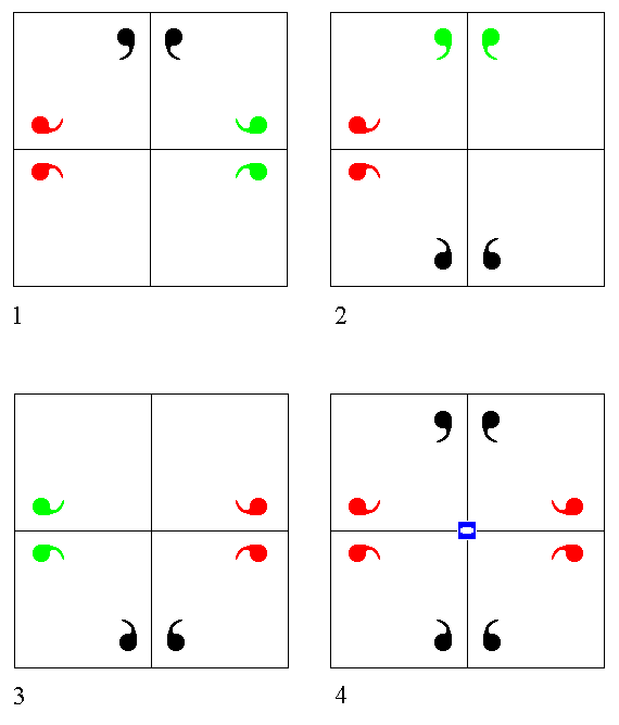
Figure 17. The motif pattern in (4) of Figure 16 implies 4-fold roto-inversion symmetry. Black motifs are upper motifs, red motifs are lower motifs. Two vertical mirror planes, perpendicular to each other are indicated by straight lines. These are the added and implied mirror planes in Figure 16 ( They are drawn rotated by 450 for convenience).
(1). We start with two upper motifs (black) which are symmetrically related to each other. To this motif pair the operation of 4-fold roto-inversion symmetry is applied : It is rotated 900 clockwise (resulting in an imaginary image (green) of it), immediately followed by an inversion through a point on the axis of rotation (i.e. the imaginary motifs are inverted) resulting in a lower real motif pair (red), which is the 4-fold roto-inversion image of the original motif pair (black). So we now have two motif pairs (black and red).
(2). Next the newly created motif pair is again subjected to the operation of 4-fold roto-inversion, resulting in an upper (third) motif pair (black).
(3). This third motif pair is in turn subjected to the operation of 4-fold roto-inversion, resulting in a lower (fourth) motif pair (red).
When we continue this process no further motifs are generated. The resulting motif pattern is depicted in (4).
(4). The emerged motif pattern is consistent with 4-fold roto-inversion symmetry about the vertical axis coinciding with the line of intersection of the two mirror planes (i.e. the axis perpendicular to the plane of the drawings). So this axis is now a 4-fold roto-inversion axis. Note that the pattern as a whole does not possess a center of symmetry. We can clearly see that this pattern is -- with respect to symmetry -- identical to the motif pattern in (4) of Figure 16. So the same conclusion holds regarding the 4-fold roto-inversion symmetry of the vertical axis.
In (5) of Figure 16 we stated that "the 4-fold roto-inversion axes generate four diagonally inclined mirror planes (indicated by continuous blue arcs)."
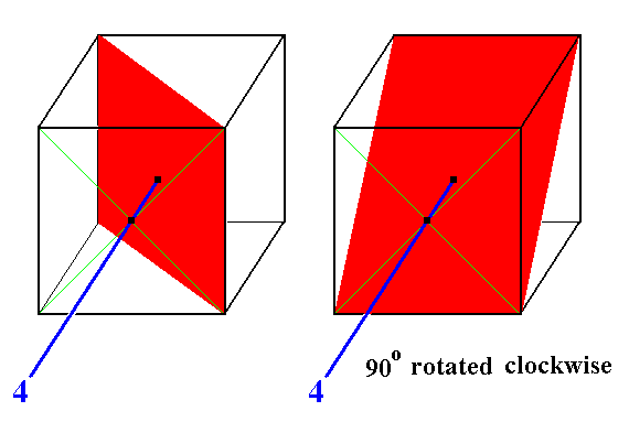
Figure 18. Here we see the action of a 4-fold rotation axis. The image of the vertical mirror plane (red) is a diagonally inclined mirror plane. A 4-fold roto-inversion axis has the same effect, because the subsequent inversion of the rotated plane (through a point on the axis in the center of the cube) leaves this plane unchanged (the swapping of its points yields the same plane). So the rotated plane is equal to the rotated + inverted plane, and consequently is the image of the roto-inversion operation.
Addition of a non-inclined vertical diagonal mirror plane to the symmetry content of Class 432 yields Class 4/m 3* 2/m. See Figure 19.
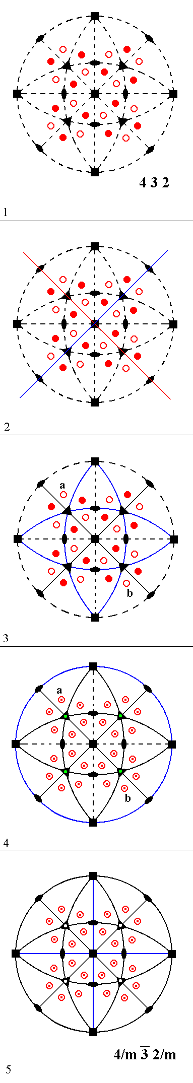 |
Figure 19. Derivation of Class 4/m 3* 2/m from Class 432 by adding a non-inclined vertical diagonal mirror plane. (1). Stereographic projection of the symmetry elements of the Class 432, and of the face poles of its most general Form. (2). Addition of a non-inclined diagonal vertical mirror plane to the symmetry content of Class 432. Existing horizontal 4-fold axes first of all generate yet another vertical diagonal mirror plane. (3). The existing 4-fold axes also generate four inclined diagonal mirror planes (See Figure 18). (4). A mirror plane containing a 2-fold axis (as do the two vertical diagonal mirror planes) implies yet another mirror plane perpendicular to it. This means that in our case a horizontal mirror plane is implied (signified by the continuous blue perimeter of the projection plane). This in turn means that the motifs (represented by face poles) are reflected in that horizontal mirror plane, and so their number is doubled. In (3) the motif pattern still does not have a center of symmetry, as can be seen with respect to, say, the motifs a and b. But here in (4) it does have a center of symmetry which again can be seen with respect to, say, the motifs a and b. This means that the 3-fold rotation axes are at the same time also 3-fold roto-inversion axes (Recall that a 3-fold roto-inversion axis is equivalent to a 3-fold rotation axis + a center of symmetry). We cannot say that the existing 4-fold rotation axes become 4-fold roto-inversion axes, because a structure having such an axis lacks a center of symmetry. The same applies to the existing 2-fold rotation axes.
(5). The horizontal 4-fold rotation axes generate two new vertical non-diagonal mirror planes (by rotating the horizontal mirror plane by 900).
The symmetry configuration is now that of Class |
Addition of a non-inclined vertical diagonal mirror plane to the symmetry content of
 |
Figure 20. Derivation of Class 4/m 3* 2/m from Class 2/m 3* by adding a non-inclined vertical diagonal mirror plane. (1). Stereographic projection of the symmetry elements of the Class 2/m 3*, and of the face poles of its most general Form. (2). Addition of a non-inclined diagonal vertical mirror plane to the symmetry content of Class 2/m 3*. Existing horizontal 2-fold axes generate yet another vertical diagonal mirror plane. (3). Two mirror planes perpendicular to each other define a 2-fold rotation axis going through their line of intersection. Two such axes are consequently implied (See arrows). The added and implied mirror planes double the number of motifs as indicated. (4). The resulting motif pattern has 4-fold rotational symmetry about the vertical axis, so this axis becomes a 4-fold rotation axis (See the small solid blue square in the center of the stereogram). (5). The 3-fold roto-inversion axes (Recall that such an axis is equivalent to a 3-fold rotation axis + center of symmetry) multiply the added and implied vertical mirror planes, resulting in four inclined mirror planes (indicated by continuous blue arcs). See Figure 21 for an explanation. Each of these new mirror planes is perpendicular to an existing vertical non-diagonal mirror plane, and in this way new 2-fold rotation axes are implied (indicated by small blue solid ellipses in the central region of the stereogram). (6). The 3-fold roto-inversion axes multiply the vertical 4-fold rotation axis, resulting in a total of three 4-fold rotation axes perpendicular to each other. The symmetry configuration is now that of Class 4/m 3* 2/m. This is a Class, already derived earlier. |
The next Figure explains what is stated in the first half of (5) of the above Figure.
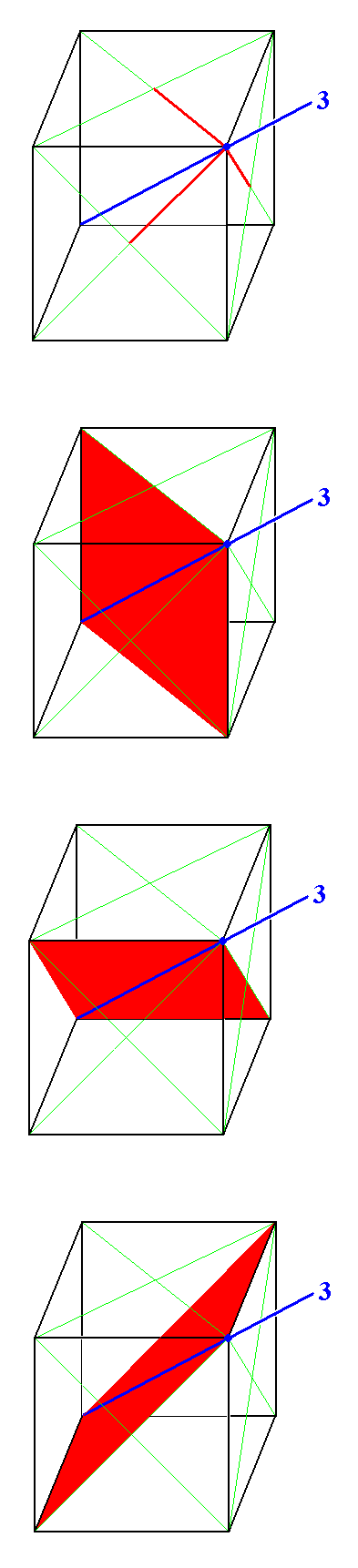 |
Figure 21.
Top image : |
Finally we must investigate the addition of a non-diagonal mirror plane -- see Figure 15 -- to the symmetry content of the five Classes we have found so far.
To continue, click HERE for Part Six.