back to homepage
The External Shapes of periodic 2-D arrays of repeated two-dimensional motifs
Rectangular Net. (continued)
We continue our investigation concerning the faces, Forms and combinations of Forms in two-dimensional crystals.
In the previous Part we considered the Crystal Class 2mm of the 2-D Rectangular Crystal System. We discussed possible faces, Forms and combinations of Forms featuring in 2-D crystals.
As has been said, this Class, i.e. the Point Group 2mm, is the translation-free residue of four (listed in Part 10) Plane Groups.
In general we can say that if we insert motifs into the empty building blocks, i.e. into the lattice, of the relevant Crystal System, one or another Plane Group is formed (defined), i.e. a periodic pattern of motifs (standing for chemical units) is formed representing one or another Plane Group.
If the motif has the same point symmetry as that of the empty building block of the crystal system, then the highest symmetrical Class of the System is formed.
If the motif has a lower symmetry than the empty building block, then a lower symmetrical Class is formed.
In the 2-D Rectangular Crystal System the two Classes 2mm and m can be formed in this way.
Within each Class there are still further possibilities as for the nature of the motifs to be
inserted :
If the motif is inserted as such, then we get for Class m the Plane Groups Pm and Cm, and for the Class 2mm the Plane Groups P2mm and C2mm.
But if the motif is in fact (i.e. when we inspect the pattern at the microscopic level) disentangled into separate motif units by (the action of) (glide) translations, then we get for the Class m the Plane Group Pg (which means that the mirror line is microscopically not a mirror line but a glide line), and (we get) for the Class 2mm the Plane Groups P2mg and P2gg.
In the Plane Group P2mg, one type of mirror line (evident in the Point Group) has become a glide line, while in the Plane Group P2gg both types of mirror lines have become glide lines.
The Plane Group C2mm distinguishes itself from the Plane Group P2mm by the fact that the 2-D lattice on which it is based, is a centered lattice, i.e. each unit mesh contains five equivalent points (a node at each corner, and a node at its center).
Let us start with the Plane Group P2mm (of the Class 2mm) and look at the possible atomic aspects presented to the environment by the possible faces.

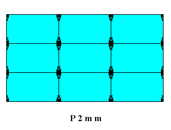
Figure 1. A two-dimensional crystal of the Class 2mm. It is a conbination of two Forms ( See Figures 13 and 14 in Part Ten). The incompleteness of the motifs at the faces expresses unsatisfied or distorted chemical valences.
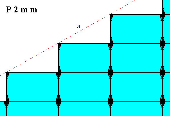
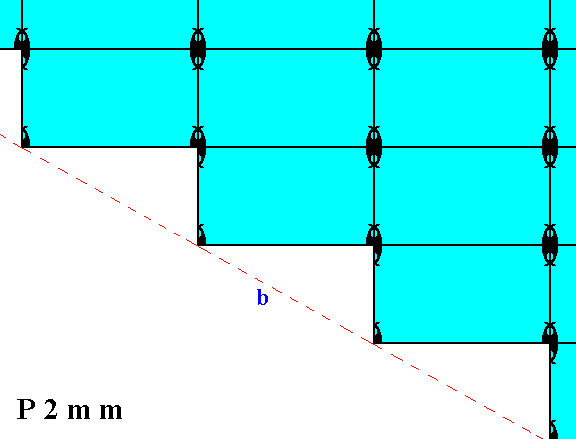
Figure 2. Atomic aspect presented to the environment by two of the faces of the Figures 16, 16a and 16b in Part Ten. The faces -- here indicated as a and b -- are symmetrically related with respect to a horizontal mirror line (through the middle of the structure (not drawn)).
In Figure 2 we can see that the horizontal mirror line (not drawn), expressing (part of) the point symmetry, goes right through the middle of the relevant meshes (building blocks). The horizontal crystallographic axis should coincide with this mirror line. As we discussed in Part Nine around the Figures 11 and 11a, the system of crystallographic axes could be chosen such that instead of going right through the relevant meshes, it coincides with the edges of those meshes, implying that the two mirror lines, expressing point symmetry elements, also coincide with those edges. In that case Figure 2 above (and something analogous applies to Figure 1) would have to be redrawn as follows (only the horizontal mirror line is drawn) :
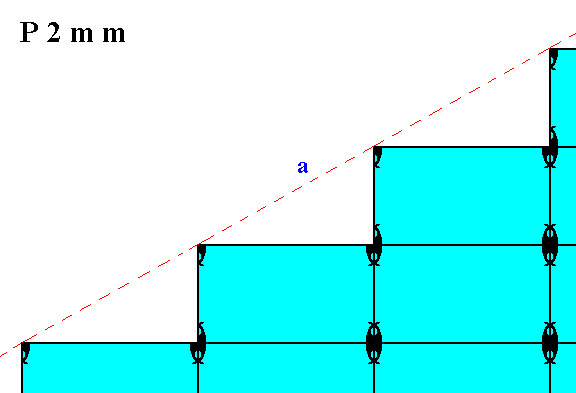
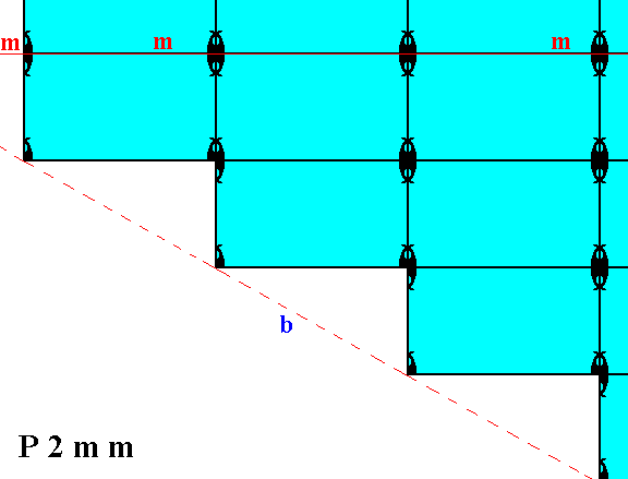
Figure 2a. Pattern of Figure 2 redrawn according to a slightly different (chosen) position of the axial system, and with that a corresponding different position of the mirror lines expressing two of the three point symmetry elements of the Class 2mm. The horizontal mirror line (m) now goes along the edges of the relevant meshes, causing the corner, made up by the faces a and b, being chopped off and so simulating a small vertical face (only detectable microscopically).
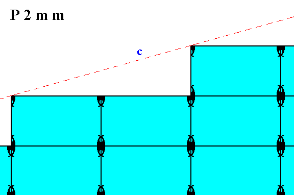
Figure 3. Atomic aspect presented to the environment by one of the faces of the Figures 18 and 18a in Part Ten.
The next Plane Group, belonging to the Point Group 2mm, we're going to consider is P2gg. In this Plane Group the motifs are disentangled according to two glide lines (which replace the mirror lines of the Point Group). If we undo this entanglement we get motifs with point symmetry 2mm. Let us see how in this case the atomic aspects presented to the environment look like.
First we will give a periodic pattern of motifs representing Plane Group P2gg :
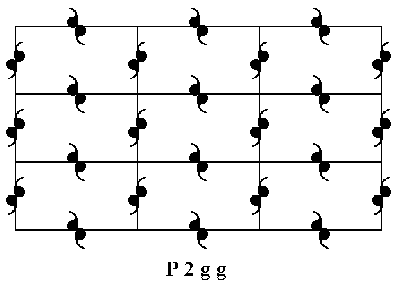
Figure 4. A pattern of repeated motifs (consisting of motif units) representing Plane Group P2gg.
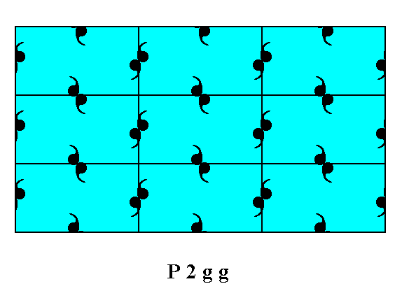
Figure 5. A two-dimensional crystal of the Class 2mm. The internal structure of it, and the nature of its motifs, express the Plane Group P2gg. We can see the atomic aspects presented to the environment by the faces of the Figures 13 and 14 in Part Ten.
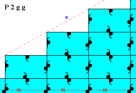
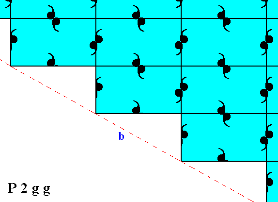
Figure 6. Atomic aspect presented to the environment by two of the faces of the Figures 16, 16a and 16b in Part Ten. The faces -- here indicated as a and b -- are symmetrically related with respect to a horizontal mirror line (m), according to the point symmetry of the present Class (2mm). The internal structure, however, does not show this symmetry. Only when we shift one half of the pattern along the horizontal and vertical glide translations (which are half the corresponding lengths of the unit mesh), the two halves of the structure become also internally symmetric with respect to a horizontal mirror line (See the next Figures), proving that the asymmetry will not be visible macroscopically.
The atomic aspect of the two faces a and b is similar but not the same. They will be the same when the described shift is actually made (See also the next Figures).
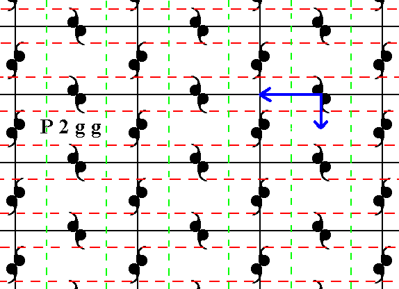
Figure 7. Patterns representing the Plane Group P2gg show -- when inspected microscopically -- two sets of glide lines. The two sets are perpendicular to each other, and are indicated by red dashed and green dashed lines respectively. Heavy arrows show the glide translation vectors. When the whole pattern (imagined as infinitely extended) is subjected to one of these vectors followed by a reflection with respect to the glide line parallel to that vector, the pattern will map onto it self. The same applies with respect to the other vector. The next Figure analyses these vectors further.
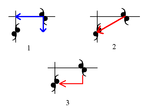
Figure 8.
(1). The glide translation vectors from Figure 7.
(2). Addition of the two vectors yields one vector equivalent to those two vectors together.
(3). Sign (red), equivalent to, and indicating the set of two vectors of (1). As such this set will be indicated in the next Figure.
The existing difference between the asymmetric situation of Figure 6 and a possible symmetric situation, can be imagined to be caused by a diagonal shift of half the diagonal of the unit mesh (according to the set of two vectors described above) of one half of the pattern of Figure 6 (say the bottom half) with respect to its other half. So if we make this shift undone (by means of the indicated vectors) we expect to obtain two symmetrical halves. Let me explain this.
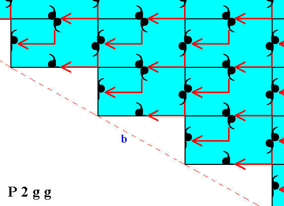
Figure 9. Indication of the diagonal shift of the bottom half of the pattern of Figure 6, in order to make it fully symmetrical with respect to its top half.
Because we shift only the bottom half, its uppermost motifs -- only partially visible -- will not themselves be the result of any shift, because otherwise some motifs of the upper half of the pattern would have been shifted while ex hypothesi they shouldn't. So we have three types of motifs :
(1). Motifs that have not been shifted, i.e. not been copied onto other motifs and replacing the latter, and are themselves also not the result of any such shift.
(2). Motifs that have been shifted, i.e. they have been copied onto other motifs while replacing the latter, and are themselves also the result of such a shift.
(3). Motifs that are copied onto other motifs imposing their shape upon them, while they themselves are not the result of any such copying from other motifs.
The motifs of (1) are from the upper half of the pattern, and the motifs of (2) are from the lower half of the pattern. The motifs of (3) do not -- in this respect -- have a definite association with one or the other half of the pattern. These motifs will therefore not comply with the symmetry of the two halves with respect to each other. But one line of deviating motifs will not be distinguished macroscopically. Also the mentioned shift is not visible macroscopically, that's why such structures look perfectly symmetrical : Macroscopically we see the glide lines as mirror lines.
The next Figure shows the result of the diagonal shift of the motifs of the lower half of the pattern of Figure 6.
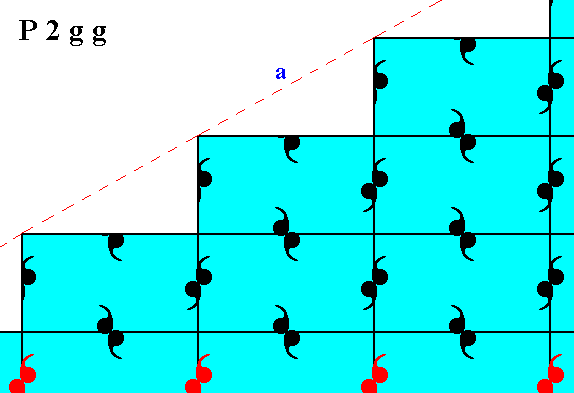
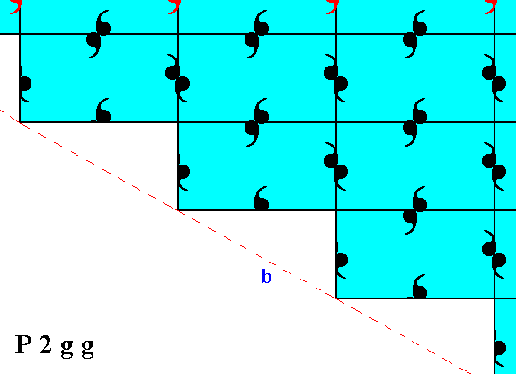
Figure 10. After a diagonal shift of the motifs of the bottom half of the pattern of Figure 6 the structure becomes -- also internally -- symmetric with respect to a horizontal mirror line going between those halves, except for one row of motifs (indicated in red).
When we do not consider the one abberant row of motifs as shown in Figure 10, we can clearly see the symmetry of the top and bottom halves with respect to each other.
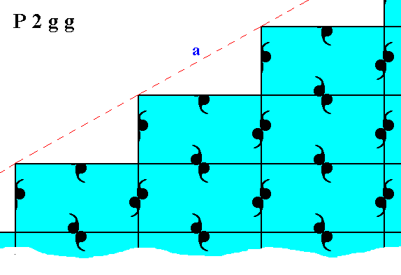
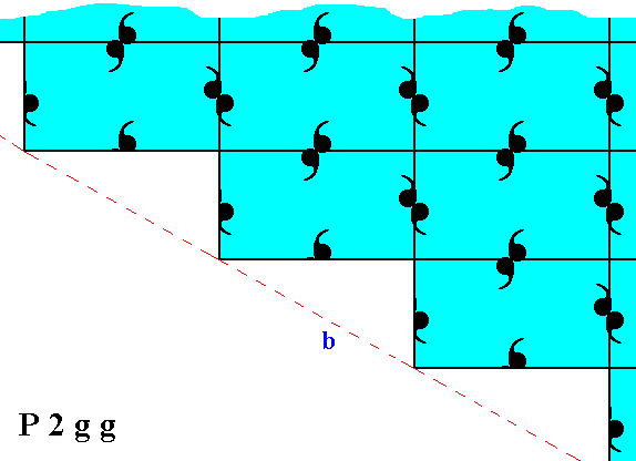
Figure 11. Total mirror symmetry (internal and external) of a fragment of a 2-D crystal of the Class 2mm, having motifs such that it represents the Plane Group P2gg.
If we let relate the top and bottom halves of the pattern of Figure 10 such that the mirror line (m) expressing the point symmetry does not go right through the relevant meshes (as in Figure 10) but instead coincides with their horizontal edges (as discussed at Figures 11 and 11a of Part Nine) then we will get a pattern in which full reflectional symmetry reigns with respect to the mirror line m. The motifs, however, lying on the horizontal mirror line (expressing one of the three point symmetry elements) are abberrant. See Figure 12.
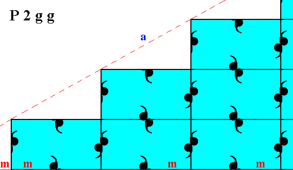
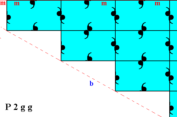
Figure 12. If the top and bottom halves of Figure 10 are aligned such that the horizontal mirror line (m), expressing part of the point symmetry of the structure, coincides with the horizontal edges of the relevant meshes of the net, then full reflectional symmetry is obtained, i.e. also the internal organization of the top and bottom halves complies with the reflectional symmetry (mirror symmetry) with respect to the horizontal mirror line(m) separating the two halves. But, as can be seen in this Figure the motifs lying on this mirror line have become abberrant. So in both cases, the present one and the one of Figure 10, there is one row of motifs that behaves differently.
The result of Figure 10 is more natural than the one in the present Figure.
The difference between Figure 10 and the present Figure boils down to the different choices of the position of the system of crystallographic axes, and with it the position of the mirror line expressing part of the point symmetry (This point symmetry is 2mm).
In Figure 12a we can see that a pattern representing Plane Group P2gg is not, according to its internal structure, mirror symmetric with respect to some vertical mid-line (which is, as was the above discussed horizontal mid-line, a point symmetry element of the present Class (2mm)).
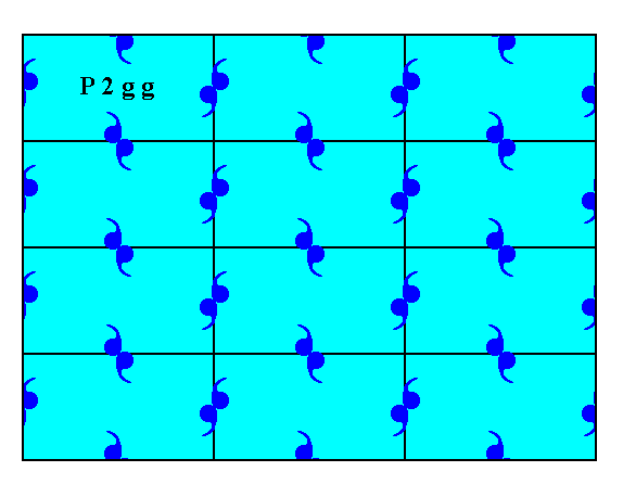
Figure 12a. The internal organization of a pattern -- depicted as a crystal -- representing Plane Group P2gg does not as such express mirror symmetry with respect to some vertical line (as one of the symmetry elements of the Class 2mm to which it belongs).
The next Figures show that a shift of the motif pattern, like the shift applied in Figure 9, can restore full mirror symmetry with respect to the above mentioned vertical mirror line (as demanded by the point symmetry of our Class, 2mm). If we shift all the motifs of the (say) right half of the pattern as indicated in the Figures, then (also) the internal structure will comply with mirror symmetry with respect to a vertical mirror line. This proves that the cause of the (initial) asymmetry of the pattern with respect to this vertical line is only related to a shift of the pattern, a shift of microscopical dimensions. And because of this the asymmetry is not macroscopically visible, and the faces of the crystal accordingly look symmetric with respect to that vertical line, the latter becoming one of the point symmetry elements of the present Class.
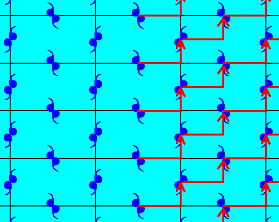
Figure 12b. The right half of a pattern representing Plane Group P2gg is shifted (translated) according to the vector indicated. The vertical mid-row of motifs is so shifted, but a copy of each of them remains in place, so they are not themselves a result of any shift.
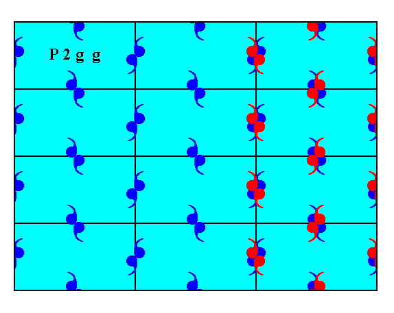
Figure 12c. Indication of the shift of motifs as specified in Figure 12b.
For the final result see the next Figure.
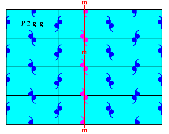
Figure 12d. After having shifted the right half of the pattern of Figure 12a according to the specifications above, we now have a pattern that is mirror symmetric with respect to the vertical line m (also) according to its internal structure except for the row of motifs (purple) that lies on that mirror line. Such a one-row discrepancy is not visible macroscopically. All this indeed shows that the initial asymmetry is caused just by a translational difference of microscopic dimensions. So that asymmetry is not visible macroscopically.
We can apply the same operation as we did in the above Figures, but now such that the vertical mirror line coincides with edges of the unit meshes, implying that the vertical crystallographic axis will now be coincident with such an edge (which is the preferred location of that axis) :
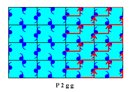
Figure 12e. Indication of the shift to be performed on the right half of the pattern representing Plane Group P2gg (now using a smaller mesh).
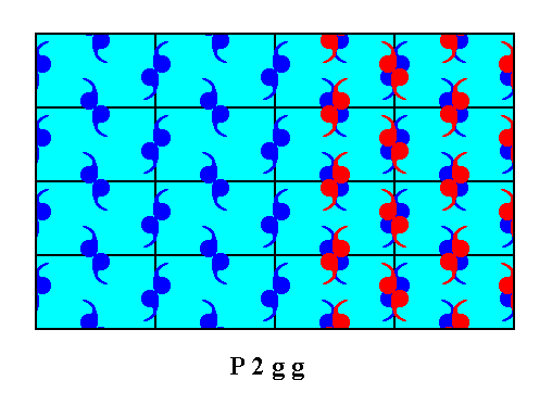
Figure 12f. The right half of the motif pattern is shifted according to the vector indicated in Figure 12e. The middle row of motifs is also so shifted, but leaves a copy of itself behind, implying that it is not itself a result of any such shift. The next Figure depicts the result.
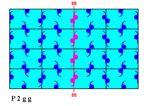
Figure 12g. After having shifted the motifs according to the specifications given above, the resulting pattern is now mirror symmetric with respect to the vertical line m , also according to the internal structure, proving that the cause of the (initial) asymmetry is just a shift of the pattern, a shift of microscopic dimensions. So this asymmetry is invisible at the macroscopical level. Only the middle row of motifs (purple) does not comply with the mentioned symmetry, but also this is macroscopically not visible.
The difference between the patterns representing Plane Group P2mm and those representing Plane Group P2gg is caused by a difference of their respective motif units, i.e. it is caused by a certain difference in the chemical content of the crystals that represent these Plane Groups.
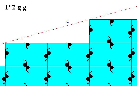
Figure 13. Atomic aspect presented to the environment by one of the faces of Figure 18 and 18a in Part Ten, in the present Figure indicated by c.
In the next Part we will consider the atomic aspects of faces belonging to patterns representing Plane Group P2mg.
To continue, click HERE for Part Twelve.
back to homepage