back to homepage
The External Shapes of periodic 2-D arrays of repeated two-dimensional motifs
Rectangular Net. (continued)
We continue our investigation concerning the faces, Forms and combinations of Forms in two-dimensional crystals.
In the previous Part we considered the Crystal Class 2mm of the 2-D Rectangular Crystal System. We discussed possible faces, Forms and combinations of Forms featuring in 2-D crystals, and their atomic aspects as they appear in the possible Plane Groups of the Class 2mm. So far we considered the Plane Groups P2mm and P2gg.
Here we will investigate the atomic aspects as they can appear in the Plane Group P2mg.
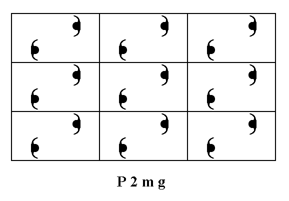
Let us first give a pattern representing Plane Group P2mg, as given earlier.

Figure 1. A pattern of periodically repeated motifs (consisting of motif units) representing Plane Group P2mg.
The several possible faces present several atomic aspects to the growing environment of the crystal. See the next Figures.
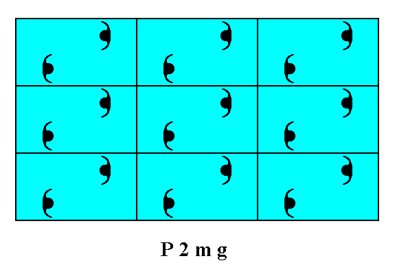
Figure 2. Atomic aspects presented to the environment by the faces (derived in the Figures 13 and 14 of Part Ten) of a two-dimensional crystal of the Class 2mm.
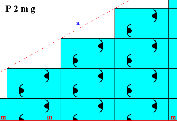
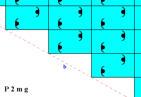
Figure 3. Atomic aspects presented to the environment by two of the faces of Figures 16, 16a and 16b in Part Ten, here indicated as a and b. The horizontal mirror line m, expressing one of the point symmetry elements (of the Point Group 2mm), goes through the relevant building blocks, but not through their mid-lines. The horizontal crystallographic axis should be chosen such as to coincide with this mirror line. From a microscopic view this position of the mirror line with respect to the (edges of the) building blocks (unit meshes) seems a little unnatural. Moreover the atomic aspects of the faces a and b are not symmetric.
The signalled unaturalness of the position of the horizontal mirror line -- expressing part of the point symmetry -- relative to the edges of the relevant building blocks, can be remedied by shifting the 2-D lattice (net) such that the horizontal edges of the meshes as well as their horizontal mid-lines coincide with mirror lines of the motif pattern. At the same time we choose this shift to be such that the result is nicely comparable with our Figures concerning the Plane Group P2gg, say, Figure 5 in Part Eleven.
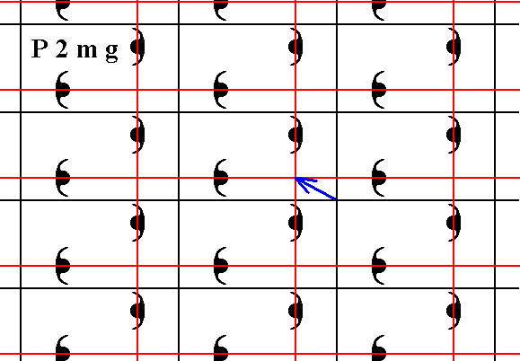
Figure 4. We shift the net such that the horizontal edges of the meshes coincide with mirror lines of the pattern, and moreover such that the result is comparable with the corresponding drawings concerning the Plane Group P2gg. The shift vector is indicated in blue, and the new net position in red. The final result is shown in the next Figure.
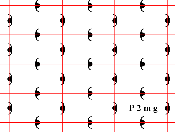
Figure 4a. The (extended) pattern of Figure 1, representing Plane Group P2mg , but with the new position of the net (Recall that a net is no more than a theoretical tool to indicate, i.e. describe, the specific periodic nature of the motif pattern). The mirror lines of the pattern now coincide with the horizontal edges of the meshes and with their horizontal mid-lines.
The system of crystallographic axes can now be chosen naturally, namely along the edges of the unit mesh while the horizontal axis coincides with a mirror line :
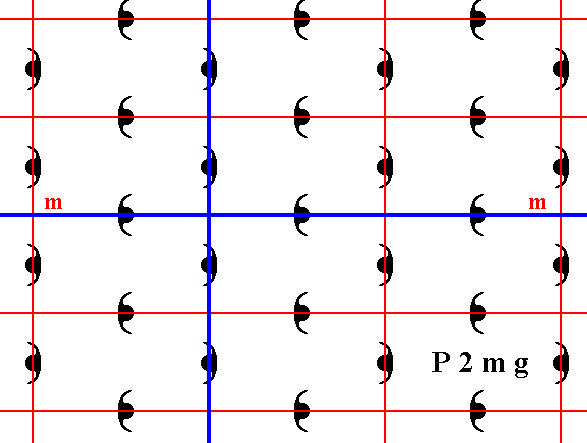
Figure 5. The axial system (indicated in blue) chosen along the edges of the unit mesh. The horizontal axis coincides with a mirror line (m) of the pattern. This mirror line also expresses part of the point symmetry of the Class 2mm.
Now we can again concentrate on atomic aspects while using the new position of the net with respect to the motif pattern.
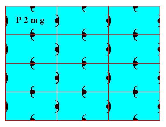
Figure 6. Atomic aspects presented to the environment by the faces (derived in the Figures 13 and 14 of Part Ten) of a two-dimensional crystal, using the new position of the net. To make this crystal fully comparable with the one depicted in Figure 2, one horizontal layer of building blocks should be added to the latter.
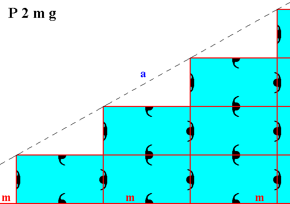
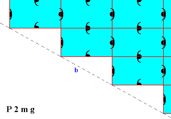
Figure 7. Atomic aspects presented to the environment by two of the faces of Figures 16, 16a and 16b in Part Ten, here indicated as a and b. The horizontal mirror line m, expressing one of the point symmetry elements (of the Point Group 2mm), goes right between the two middle rows of relevant building blocks, and coincides with horizontal edges of them. The horizontal crystallographic axis should be chosen such as to coincide with this mirror line. Compare with Figure 3. From a microscopic view this position of the mirror line with respect to the (edges of the) building blocks (unit meshes) looks natural. The atomic aspects of the faces a and b are symmetric with respect to the mentioned mirror line.
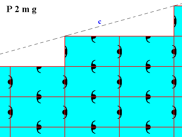
Figure 8. Atomic aspect of one of the faces of the Figures 18 and 18a in Part Ten.
The next Figure is like Figure 6, but now a somwhat smaller mesh is used. According to the Class to which this pattern belongs there is a vertical mirror line such that the left and right faces are symmetrical with respect to that line. But, as can be seen from the Figure, the internal structure does not support this. The cause of this asymmetry is however related to just a microscopical shift (translation) of part of the motif pattern, and is consequently not visible at the macroscopical level. See The next Figures.

Figure 8a. A pattern representing Plane Group P2mg, depicted as a 2-D crystal. The vertical mirror line, as one of the symmetry elements of the present Class, is not evident at the microscopic level.
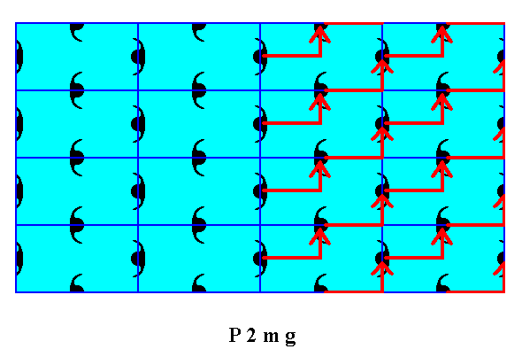
Figure 8b. When we shift the right hand half of the pattern of Figure 8a according to the vector indicated, these halves will become mirror symmetric with respect to a vertical line separating those halves, also (symmetric) according to the internal structure, proving that the asymmetry is caused just by a translational shift of microscopic dimensions. This asymmetry is consequently not visible at the macroscopic level.

Figure 8c. Indication of the shift of motifs as specified above.
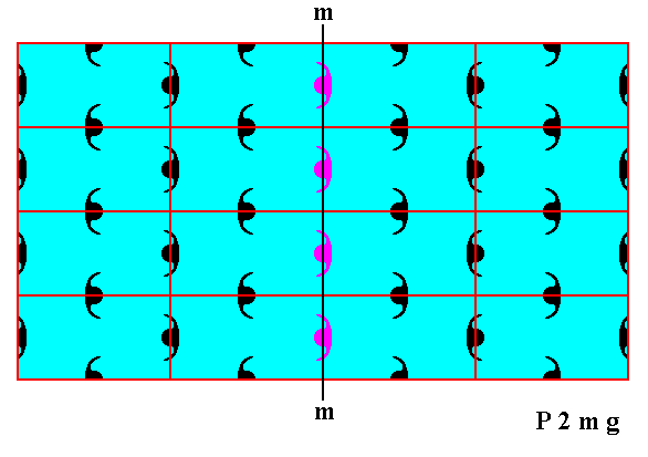
Figure 8d. Result of the above specified shift of motifs. The pattern is now mirror symmetric with respect to the vertical line m , also according to the internal structure except for the column of motifs (purple) lying on the line m . Because the shift has only microscopical dimensions, and because the left-over asymmetry concerns only one motif column, the asymmetry in the crystal, with respect to line m -- evident in the internal structure -- is macroscopically invisible.
The difference between the patterns representing Plane Group P2mg and patterns representing Plane Group P2gg is caused by a difference in motifs, and consequently by a difference in chemical content. To see this clearly we reproduce Figure 6 (of the present Part) of a 2-D crystal representing Plane Group P2mg, and an adapted version (namely one row of building blocks added) of Figure 5 in Part Eleven, of a 2-D crystal representing Plane Group P2gg :
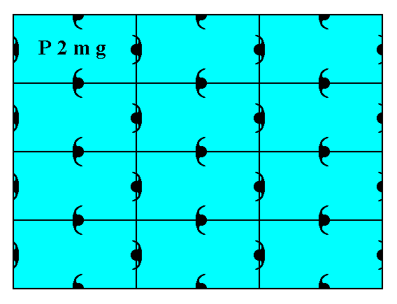
Figure 9. A 2-D crystal, with its internal organization representing Plane Group P2mg.
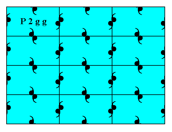
Figure 10. A 2-D crystal, with its internal organization representing Plane Group P2gg.
In both cases the distribution of motif units is the same, and can be described by stating that each node of a primitive rectangular net is surrounded by four motif units, but such that for each node pair of horizontally or vertically adjacent nodes one of the four motif units is common (i.e.commonly possessed by both members of such a pair). So the only difference is indeed the motif units themselves, and this can be translated into a chemical difference.
The last Plane Group belonging to the Class 2mm of the 2-D Rectangular Crystal System is the Plane Group C2mm.
Let us first give a pattern representing this Plane Group, as given earlier :
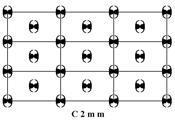
Figure 11. A pattern of periodically repeated motifs representing Plane Group C2mm.
The several possible faces of crystals of this Plane Group show several atomic aspects to the growing environment.
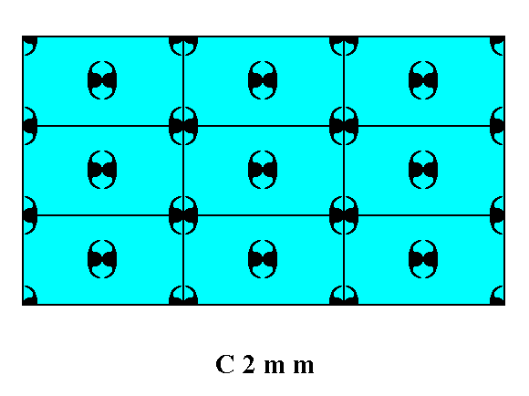
Figure 12. Atomic aspects presented by the faces (derived in Figures 13 and 14 in Part Ten) of a 2-D crystal of the Class 2mm and Plane Group C2mm.
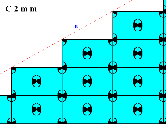
Figure 13. Atomic aspect presented to the environment of one of the faces of Figures 16, 16a and 16b in Part Ten.
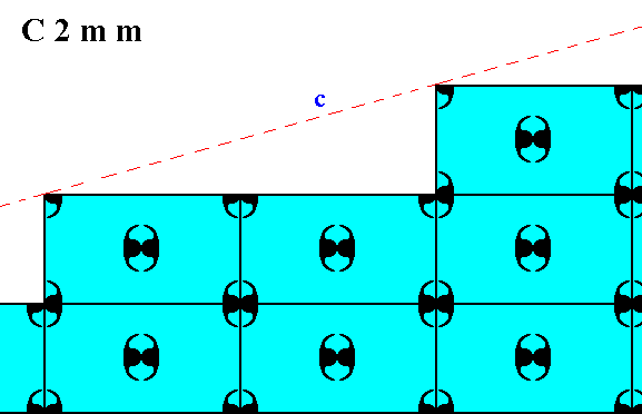
Figure 14. Atomic aspect of one of the faces of the Figures 18 and 18a in Part Ten.
Now we have discussed exhaustively all the Plane Groups belonging to Class 2mm, and with it we are done with the 2-D Rectangular Crystal System.
In the next Part we will consider the 2-D Tetragonal Crystal System, its Classes, crystal faces, Forms and combination of Forms. Further we will discuss its Plane Groups and the atomic aspects presented to the environment by the possible crystal faces within this System.
To continue, click HERE for Part Thirteen.
back to homepage