e-mail :

Sequel to Group Theory
We'll start with reminding the reader about the "Important Remark" near the end of Part III of Group Theory (To see it, click HERE and then go to (end of) Part III ), a Remark concerning the direction of reading products of group elements, like, say, apq. We read such products (from that Remark onwards) from back to front. Thus (with respect to apq) first q, then p, and then a.
Infinite two-dimensional periodic patterns, or Ornaments (sequel)
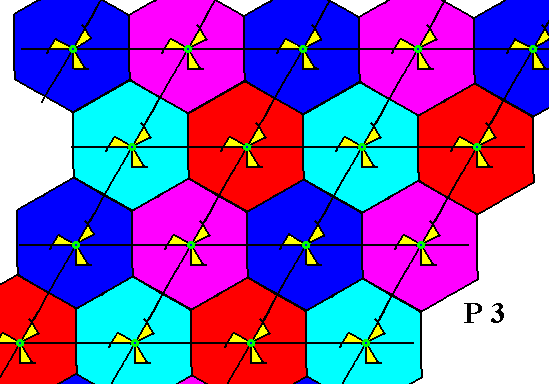
The next plane group to be discussed with respect to the interpretation of the center of the motif s.str. is the group P3 .
Figure 1. Pattern representing the plane group P3 . At each lattice point we see a 3-fold motif s.str. . Motifs s.l. are indicated by the hexagons (plus content).
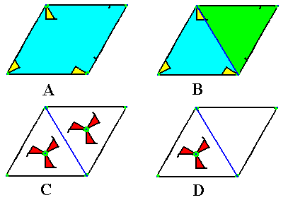
Figure 2.
Image A : A lattice mesh is isolated from the pattern of Figure 1.
Image B : The rhombic lattice mesh consists of two equilateral triangles, both containing in their center a 3-fold rotation axis. As can be seen, these centers are not equivalent points.
Image C : Because of the 3-fold nature of the content of the two triangles, we can replace the existing motifs s.str. by a 3-fold motif, placed in the center of the triangle, in such away that they will not relate to each other by reflection or glide reflection. This can be guaranteed by letting the two motifs relate to each other by a translation (eliminating -- by doing so -- all indirect symmetry transformations).
Image D : But by replacing the existing motif s.str. by a 3-fold motif in the center of one of the two triangles making up the rhombic lattice mesh, the 3-fold rotation axis in the empty triangle is automatically implied by the surrounding motifs of the pattern (each inside a triangle of a mesh, while letting the other triangle of that mesh empty). We will see that both C and D will yield a P3 pattern when translated indefinitely along the two generating translations of the lattice mesh. Both resulting patterns will be seen to be equivalent, i.e. both are P3 patterns.
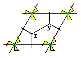
Figure 3. The points x and y are not equivalent. Moreover they are also not equivalent to the lattice points (otherwise they would themselves also be lattice points).
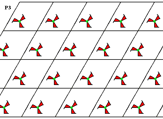
Figure 4. Pattern generated from the mesh D of Figure 2. It is a P3 pattern.
The next Figure shows that the 3-fold rotation axis in the center of each empty triangle is indeed implied by the surrounding features of the pattern of the previous Figure.
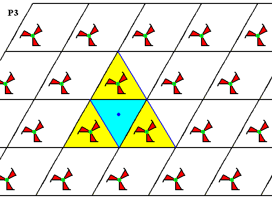
Figure 5. The center of each empty triangle in the P3 pattern of the previous Figure has a 3-fold rotation axis : After rotation of 1200 or 2400 the motifs keep the same appearance.
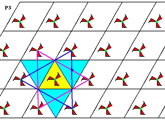
Figure 5a. Same pattern as previous Figure. The center of the other (non-empty) triangle also coincides with a 3-fold rotation axis.
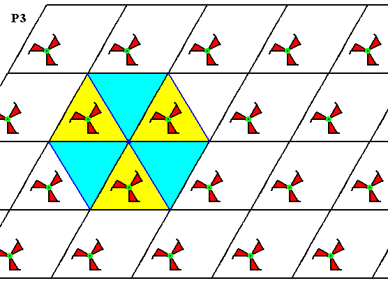
Figure 5b. As shown for one, each lattice point is the seat of a 3-fold rotation axis.
The three above Figures show that the pattern, generated from D of Figure 2, has a 3-fold rotation axis at each lattice node and one inside every triangle (two of which make up a rhombic unit mesh). Because the rotational motifs (3-fold swastica's) all have the same orientation, indirect symmetries (reflections and glide reflections) cannot be present. All this proves that the present pattern is indeed a P3 pattern.
The next Figure shows a pattern generated by a unit mesh containing two 3-fold motifs.
Figure 6. Pattern generated by the mesh C of Figure 2. It also is a P3 pattern.
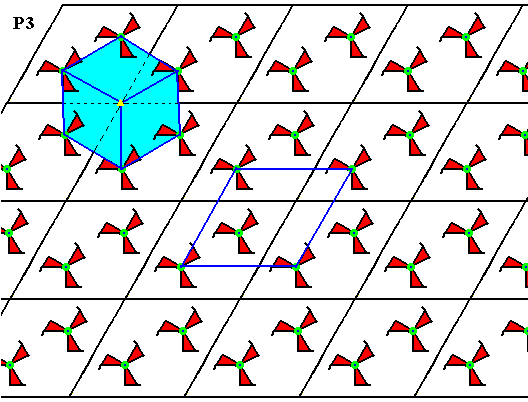
Figure 7. Same pattern as in Figure 6.
Four equivalent points are indicated. They themselves also form a hexagonal lattice.
It is further indicated that the lattice points represent 3-fold rotation axes.
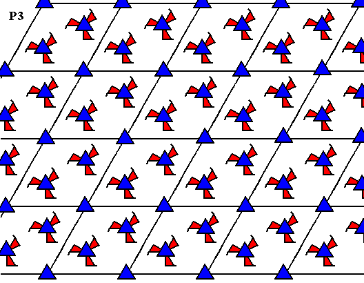
Figure 8. Same pattern as in the two previous Figures.
All the locations of the 3-fold rotation axes are indicated. Their pattern fully complies with that of a P3 ornament : One 3-fold axis at each lattice node (i.e. at each corner of the rhombic lattice mesh), and two inside the lattice mesh. And because the rotational motifs (3-fold swastica's) all have the same orientation, there cannot be indirect symmetries, i.e. there are no reflection lines, nor glide lines present in the pattern.
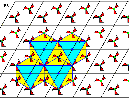
Figure 9. Same pattern as in the previous three Figures.
We can see that each lattice point is in fact associated with a three-fold motif. Such a motif is indicated by a regular hexagon but with alternate content, which indicates its trigonal nature (emphasized by the inserted -- i.e. drawn -- equilateral triangle). So the pattern is in fact equivalent to that of Figure 1.
So in both cases (C and D in Figure 2) we end up with a genuine P3 ornament.
In the pattern of Figure 6, i.e. the dense version of the P3 pattern, we see that the lattice points represent 3-fold rotation axes. So without changing the pattern's symmetry we can insert 3-fold motifs onto these lattice points. We must take care that the inserted motifs are not mirror images of the other motifs, in order not to induce mirror lines. See next Figure.
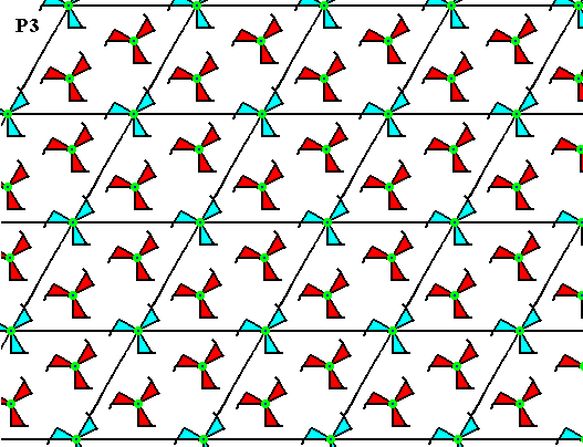
Figure 10. Insertion of extra motifs onto the lattice nodes of the P3 (dense) pattern of Figure 6. These extra motifs are highlighted by the color blue. This color does, however, not signify any asymmetry. The pattern -- still a P3 pattern -- has now become still more dense. But, see next Figure.
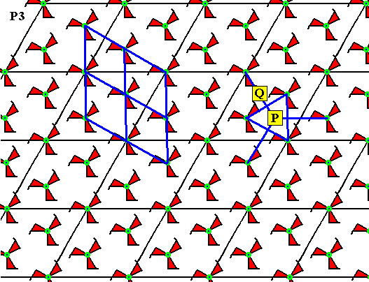
Figure 11. The P3 pattern of the previous Figure.
We can see that the points P and Q are locations of 3-fold rotation axes. They should not be there for a P3 pattern. A unit mesh of such a pattern has 3-fold rotation axes at its corners and two inside it. And now there seem to be four such axes inside the unit mesh. The conclusion therefore is that now the mesh is not a unit mesh anymore. In fact -- as can be seen in the left half of the drawing -- the appropriate meshes are much smaller, and we see that the pattern is identical to our initial version of a P3 pattern, as depicted in Figure 1 (where we have to ignore the boundaries of the hexagonal motifs s.l. ). So the present version is not really a denser version, but one drawn on a smaller scale.
So the group P3 admits of two versions with the same motifs or motif units. One relatively open (Figure 1 and Figure 4) and one which is more dense (Figure 6).
And of course, when we admid of different, but still 3-fold motifs (s.str), there are much more possible P3 patterns. But this applies to all symmetry groups.
We will now determine a possible fundamental region. We can choose between several shapes of the fundamental region of a P3 pattern because there are no mirror lines. We will do so with the pattern of Figure 4.
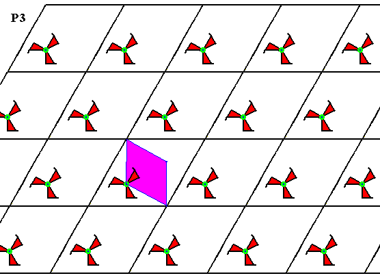
Figure 12. Fundamental region (purple) of the P3 pattern of Figure 4. It contains one asymmetric unit of the motif s.str. , and it can tile the plane, and can therefore represent a group element.
The orbit of the fundamental region generates a tiling of the plane with copies of this region. They can represent group elements. See next Figure.
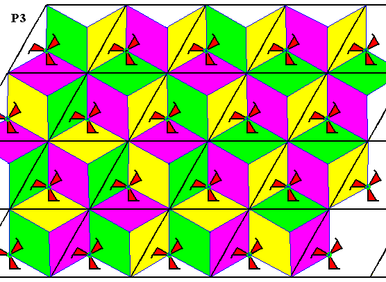
Figure 13. Tesselation of the plane by the fundamental region and its copies (generated by the symmetry transformations) of the P3 pattern (previous Figure). The colors do not signify symmetry features but only serve to highlight the fundamental regions.
Because the group P3 has no reflection lines, the shape of the fundamental region is not fixed (as it is, for example, in the group P3m1). The only condition for it to be a fundamental region is that it represents the basic asymmetric pattern unit that is multiplied by the symmetry transformations and in this way generating the whole pattern (i.e. its orbit forms the whole pattern, without gaps or overlaps), which implies that such a (fundamental) region tiles the plane completely.
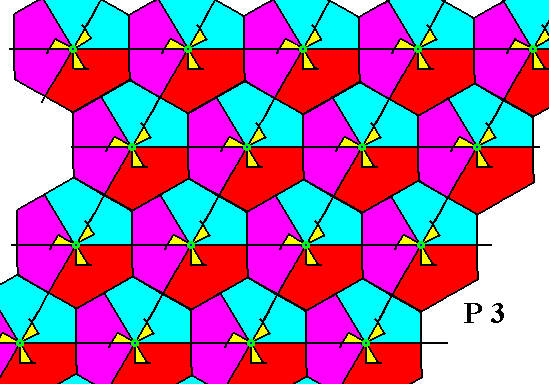
Figure 14. Alternative fundamental region of the plane group P3 . The colors do not signify symmetry features but only serve to highlight the fundamental regions. In this image of the P3 pattern the centers of the motifs s.str. are taken to coincide with the lattice nodes (For the fundamental region and its possible shapes, this is immaterial).
The plane groups P31m and P3m1 are already (Part VII) discussed with respect to the interpretation of the motifs s.str., so we will only summarize the results.
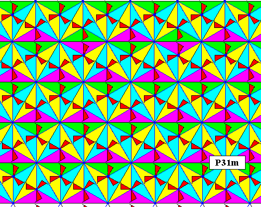
Figure 15. Tiling of the plane by the fundamental region and its copies of a P31m pattern. The colors only serve to indicate all these fundamental regions. Each fundamental region contains exactly one asymmetric unit of the motif s.str. , therefore each such region can represent a group element.
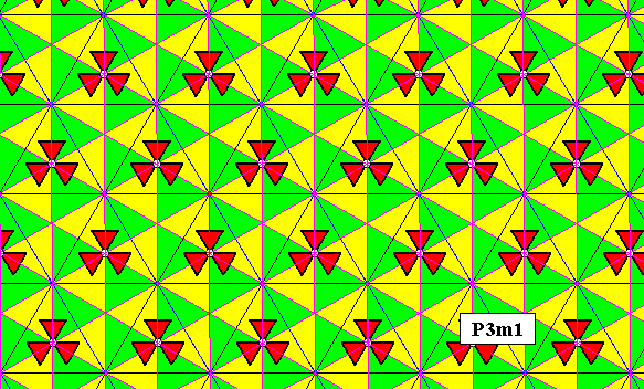
Figure 16. Fundamental region and its copies (yellow and green) of a P3m1 pattern. Each such region contains one asymmetric unit of the motif s.str. . Therefore it can represent a group element.
The next plane group to be discussed is the group P6 .
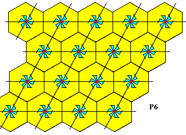
Figure 17. A pattern according to the planegroup P6 .
The motifs s.str. are conceived as having their centers coincide with the lattice nodes. So each corner of the rhomb-shaped lattice mesh is associated with such a motif s.str.. The hexagonal cells in the Figure outline the motifs s.l. of the pattern.
If we isolate a lattice mesh from the image of the above Figure, we can see that each such mesh consists of two equilateral triangles, the centers of which harbor a 3-fold rotation axis. Said differently : The content of each such triangle has C3 symmetry (and, seen from the center of each triangle, the whole pattern remains undistinguished when rotated 1200 or 2400). The next Figure shows the two triangles of an isolated lattice mesh.
Figure 18. Isolated unit mesh from the previous Figure. The mid-points of the triangles are centers of 3-fold rotation.
From the above Figure it is clear that we can legitimately -- i.e. without changing the symmetry -- replace the 6-fold motifs s.str. as they are at the lattice points, by 3-fold motifs s.str. placed at the mid-points of the triangles that make up the rhombic lattice meshes. The two 3-fold motifs in one and the same rhombic mesh must be rotated 600 with respect to each other. See next Figure.
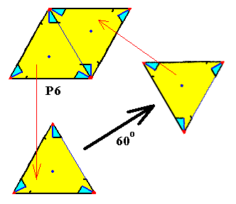
Figure 19. The content of each of the two triangles making up a rhombic unit mesh has 3-fold symmetry, while both contents are 600 rotated with respect to each other. So we can legitimately replace those contents by 3-fold motifs, placed in the two triangles of the mesh and rotated 600 with respect to each other. The unit mesh, so constructed can then be multiplied along the generating translations of the P6 pattern. See next Figure.
This next Figure thus gives a pattern, (also) according to the group P6 , with the centers of the motifs s.str. seen as located in the centra of the equilateral triangles that make up half a rhombic lattice mesh.
Figure 20. A pattern representing the plane group P6 . It has its three-fold motifs s.str. at the mid-points of the equilateral triangles that make up the rhombic unit meshes of the hexagonal point lattice. A lattice mesh is indicated (green).
Because the mid-points of the equilateral triangles are centers of 3-fold rotation (while the lattice nodes are centers of 6-fold rotations) we can replace the above 3-fold motifs (3-fold swastica's) by 6-fold motifs (6-fold swastica's) (because these also have 3-fold rotations), resulting in a pattern that has these 6-fold motifs at the mid-points of the triangles and is still a P6 pattern. See next Figure.
Figure 21. A pattern of six-fold motifs representing the plane group P6 . A lattice mesh is indicated (green).
The next four Figures show, for the pattern of the above Figure, respectively, the 6-fold rotation axes at the lattice points, the 3-fold rotation axes at the mid-points of the triangles making up the rhombic meshes, and the 2-fold rotation axes at the mid-points of the sides of the meshes and in their center :
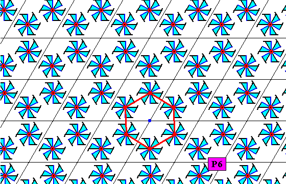
Figure 21a. At each lattice node of the pattern of the above Figure (Figure 21) there is a 6-fold rotation axis as a symmetry element of the pattern.
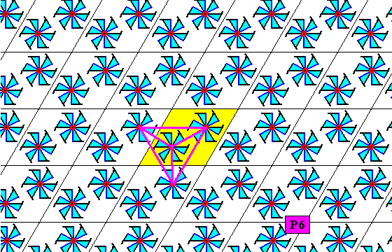
Figure 21b. At the mid-point of each lower triangle (with un upper triangle making up a rhombic unit mesh) of the pattern of Figure 21 there is a 3-fold rotation axis as a symmetry element of the pattern.
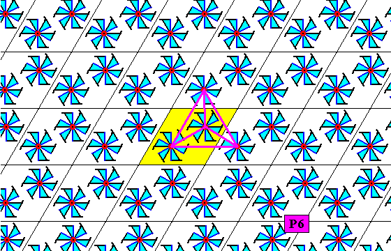
Figure 21c. At the mid-point of each upper triangle (together with a lower triangle making up a rhombic unit mesh) of the pattern of Figure 21 there is a 3-fold rotation axis as a symmetry element of the pattern.
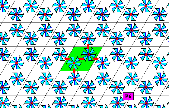
Figure 21d. At the mid-point of each side of the rhombic meshes of the pattern of Figure 21, and in their centers, there is a 2-fold rotation axis (indicated by a small red solid ellipse) as a symmetry element of the pattern.
And because the rotational motifs (6-swastica's) all have the same orientation, indirect symmetries (reflections and glide lines) are excluded. All this proves that the pattern of Figure 21 is a genuine P6 pattern.
We, however, prefer the first type of pattern (with 3-fold motifs [Figure 20]), because it is more simple and more pregnant.
The next Figure shows that the 3-fold motifs as they are placed in Figure 20 imply 6-fold rotation centers at the lattice nodes.
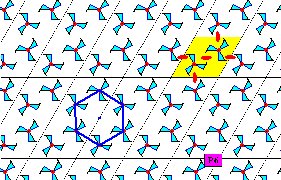
Figure 22. The three-fold motifs as they are placed in Figure 20 imply six-fold rotation centers at the lattice nodes of the P6 pattern. The pattern has also half-turns as indicated (small red solid ellipses). Together with the presence of 3-fold rotation axes in the two triangles of a rhombic unit mesh (as established earlier) this proves that the present pattern is a genuine P6 pattern.
The next Figure gives a possible choice of the fundamental region for the P6 pattern of Figure 20.
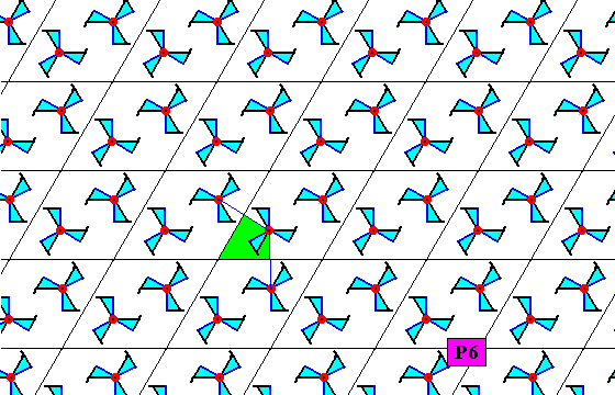
Figure 23. Fundamental region (green) of the P6 pattern of Figure 20. It contains one asymmetric unit of the motif s.str. and can tesselate the plane, and so it, and its copies, can represent group elements.
The next Figure shows the tesselation of the plane in virtue of the orbit of the fundamental region.
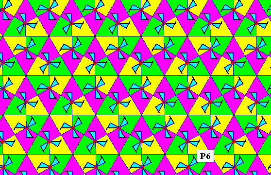
Figure 24. Tesselation (tiling) of the plane by the fundamental region of the P6 pattern of Figure 20. Each tile contains one asymmetric unit of the motif s.str. . Therefore they can represent group elements. The colors do not signify symmetry features, but only serve to highlight the tiles.
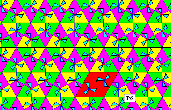
Figure 25. Same as previous Figure. A unit mesh is indicated (red).
It is interesting to note that some patterns, although belonging to different plane groups, look much alike. They are distinguished only by some subtle differences. Compare for example the P3 pattern of Figure 6, which is the dense version of the P3 pattern of Figure 4, further, the P6 pattern of Figure 20, and, finally the P31m pattern of Figure 6 in Part VII. All three are patterns based on a hexagonal point lattice which consequently displays rhombic lattice cells. All three patterns have three-fold motifs. And for all three patterns these motifs are (only) at the mid-point of the equilateral triangles making up the rhombic cells (meshes), resulting in each rhombic cell having two 3-fold motifs (s.str.) in their interior, and only there. There are several further features apparent :
The last plane group to be discussed with respect to the interpretation of its motifs s.str. is the group P6mm .
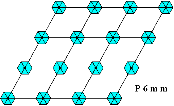
Figure 26. Pattern representing the plane group P6mm . The motifs s.str. are interpreted as D6 structures placed at the lattice points, i.e. having their centers coincide with the lattice points. As in all previous cases, the pattern must be imagined to extend indefinitely over the plane.
The next Figure shows that if we consider the centra of these same (i.e. retaining the same configuration of features of the pattern) motifs s.str. to lie at the mid-points of the equilateral triangles making up the rhombic lattice meshes, these centra are then 3-fold, i.e. they are the locations of 3-fold rotation axes (instead of 6-fold).
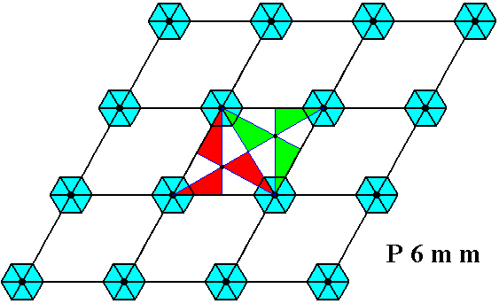
Figure 27. While the lattice points (corners of the rhombic meshes) are the seats of 6-fold rotations as symmetry transformations of the pattern, the mid-points of the triangles, making up the rhombic meshes, are the seats of 3-fold rotation as symmetries of the pattern.
But, there are also mirror lines going through the triangles, effecting them to be D3 structures. See next Figure.
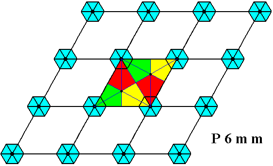
Figure 28. Each triangle -- being half a rhombic mesh underlying the P6mm pattern -- has, in addition to a 3-fold rotation axis through its center, three mirror lines intersecting in the latter. As the rotation, these mirror lines are symmetries not only of the triangle, but of the whole pattern. The result is that we can (also) view our motifs s.str. as having their centers not at the lattice points but at the mid-points of the triangles. But so conceived, they are D3 structures (instead of D6 structures, which they are when conceived as having their centra coincide with the lattice points). And because -- as can be seen in the present Figure -- the two triangles, making up a rhombic mesh, are rotated 600 with respect to each other, the corresponding D3 motifs are also rotated 600 with respect to each other.
As we can conclude from the foregoing (Figures 27 and 28), we can replace the 6-fold motifs s.str.(having D6 symmetry) at the corners of the lattice meshes, by 3-fold motifs (having D3 symmetry) at the mid-points of the equilateral triangles making up the rhomb-shaped unit cells (meshes). The three-fold motifs in a rhombic mesh must be rotated 600 with respect to each other. See next Figure.
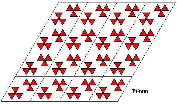
Figure 29. A pattern according to the plane group P6mm .
Each rhombic lattice mesh contains two D3 motifs s.str. that are rotated 600 with respect to each other. The pattern must be imagined to be extended indefinitely over the plane.
In the above Figure one can clearly see that the lattice points are still the seats of 6-fold rotation axes of the pattern. The next Figure shows the mirror lines that are present at each lattice point.
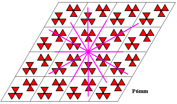
Figure 30. The six mirror lines intersecting in a lattice point (Every lattice point is the intersection point of six such mirror lines) of the P6mm pattern of the previous Figure.
The previous two Figures show that indeed we could legitimately (i.e. without changing the symmetry content) eliminate the D6 motifs at the lattice points, after we had inserted the D3 motifs at the centers of the equilateral triangles making up lattice meshes, because the D6 symmetry at the lattice points is automatically implied by the D3 motifs.
The next two Figures show the three mirror lines that go through the center of the motif s.str. located in one or the other equilateral triangle which is half a rhombic unit mesh. Together with the 3-fold rotation axis, this confirms the D3 nature of the motif s.str.
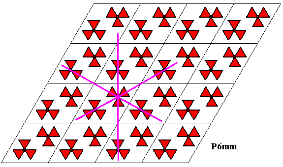
Figure 31. The three reflection lines going through the upper motif s.str. of a unit mesh of the P6mm pattern.
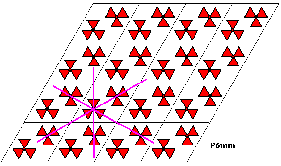
Figure 32. The three reflection lines going through the lower motif s.str. of a unit mesh of the P6mm pattern.
The next Figure shows the fundamental region of the P6mm pattern. Its shape is fully determined by three reflection lines.
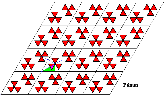
Figure 33. Fundamental region (green) of the P6mm pattern of the previous Figures. It contains one asymmetric unit of the motif s.str. and is determined by three mirror lines.
The next Figure depicts the tesselation of the plane by the orbit of the fundamental region of the P6mm pattern.
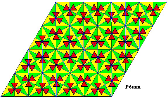
Figure 34. Tesselation of the plane by the fundamental region and its copies (yellow, green) under the group P6mm . Each of such a region contains one asymmetric unit of the motif s.str. and can therefore represent a group element. The colors do not signify symmetry features.
The next Figure is the same as the previous one, but highlights a rhombic unit mesh of the hexagonal point lattice.
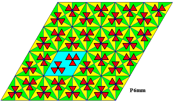
Figure 35. A unit mesh of the lattice of our P6mm pattern is highlighted (blue).
As a general remark -- concerning all ornaments G2 -- we can add the following :
This concludes our exposition of the 17 plane groups with respect to the interpretation of their motifs s.str.
In the next document we will pick up our investigation about subgroups, antisymmetry and colored symmetry, now with respect to these 17 plane groups (Earlier we had done so with the seven line groups -- friezes).
e-mail : 
To continue click HERE for further group theoretic preparation to the study of the structure of three-dimensional crystals (crystallography) and the basic symmetry of organisms (promorphology)
Back to 3-dimensional crystals (conclusion), Organic Tectology and Promorphology
Back to subpatterns and subgroups (introduction)
Back to subpatterns and subgroups Part II
Back to subpatterns and subgroups Part III
Back to subpatterns and subgroups Part IV
Back to subpatterns and subgroups Part V
Back to subpatterns and subgroups Part VI
Back to subpatterns and subgroups Part VII
Back to subpatterns and subgroups Part VIII
Back to subpatterns and subgroups Part IX