
e-mail :

Sequel to Group Theory
We'll start with reminding the reader about the "Important Remark" near the end of Part III of Group Theory (To see it, click HERE and then go to (end of) Part III ), a Remark concerning the direction of reading products of group elements, like, say, apq. We read such products (from that Remark onwards) from back to front. Thus (with respect to apq) first q, then p, and then a.
Infinite two-dimensional periodic patterns, or Ornaments (sequel)
After having done some extra theorizing with respect to the 17 plane groups, we will now investigate their possible antisymmetries and subgroups.
We will start with a pattern representing plane group P1 .
In forming antisymmetry groups we will interpret the antiidentity transformation e1 as the color permutation (Red Blue) (cycle notation), which means that when the initial color is blue it will change to red, and if the initial color is red, it will change to blue. In other words, we have to do with the dual quality red--blue. As always, the period of e1 is 2, which means that e12 = 1 (which in turn means : no color change). Further it is so that e1 commutes with every element of the generating group, but is itself not an element of the resulting antisymmetry group. And because e1e1 = 1 = e1e1-1 , we know that e1-1 = e1 .
The next Figure depicts a P1 pattern with blue as the initial color of the background, and red the initial color of the motif s.str.
Figure 1. Pattern representing plane group P1 . The initial color of the motifs s.str. (commas) is set to be red, while that of their background is set to be blue. The identity element is chosen to be represented by the area (plus content) indicated by 1 .
Now we will derive from this pattern an antisymmetry group by replacing the horizontal generating translation t by the antisymmetry transformation e1t . This implies that (where "==>" means "becomes") :
t ==> e1t .
t2 ==> e1te1t = e12 t2 = t2 .
t3 = t2t ==> t2e1t = e1t3 .
t4 = t2t2 ==> t4 .
etc.
t-1 ==> (e1t)-1 = t-1e1-1 = e1t-1 .
t-2 = t-1t-1 ==> e1t-1e1t-1 = e12 t-2 = t-2 .
t-3 = t-2t-1 ==> t-2e1t-1 = e1t-3 .
etc.
The second (oblique) generating translation is set not to be replaced, so wherever a t with an odd exponent appears in a group element symbol, the existing color must be changed according to the permutation (Red Blue) , which here means that the colors as they are of the identity element 1 , namely red for the motif s.str. (comma), and blue for its background, must be changed according to that permutation. Where no e1 appears in a group element symbol we have to do with the identity permutation, i.e. no colors will be changed.
The next Figure gives the result of all this.
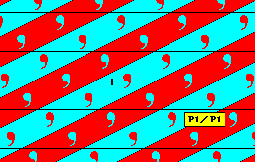
Figure 2. Pattern representing the antisymmetry group P1 / P1 derived from the generating symmetry group P1 , according to the generator set {e1t, T} , where e1 is the color permutation (Red Blue) , t the horizontal generating translation, and T the oblique generating translation.
In the above Figure we can see that the elements in the blue strips form a subgroup of the group P1 with a structure that is isomorphic to the group P1 . (The generator elements of this subgroup are t2 and T ). Therefore the group symbol for the presently derived antisymmetry group is P1 / P1 .
Every derivation of an antisymmetry group will be concluded by giving the p o i n t l a t t i c e underlying a pattern representing the derived antisymmetry group. The point lattice is a regular array of points (normally indicated by the intersections of connection lines) representing equivalent regions of the pattern and indicates the way in which a certain structural unit is periodically (i.e. with orientations conserved) repeated throughout the relevant space (in our case the 2-dimensional plane). Such a unit is generally called a unit cell, but in the 2-D case we call it a unit mesh. The geometry of the unit mesh determines the lattice type ( For 2-D : oblique lattice, rectangular lattice, centered rectangular lattice [equivalent to a rhombic lattice], square lattice, hexagonal lattice). We will see that in some cases the unit mesh of an antisymmetry pattern is larger than that of the corresponding generating symmetry patttern.
The next Figure shows the point lattice underlying the above derived antisymmetry pattern.
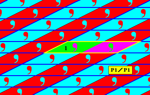
Figure 2a. Point lattice (indicated by dark blue connection lines) of the above derived P1 / P1 antisymmetry pattern. A unit mesh is indicated by yellow lines and alternative colors. Compare with the lattice underlying the pattern representing the generating symmetry group P1 in Figure 1.
The next Figure gives an example of the antisymmetry group P1 / P1 from Neolithic art.
Figure 3.
Top image : Pattern representing the generating group P1 .
Bottom image : Antisymmetry ornament P1 / P1 from Neolithic art. (After JABLAN, 2002)
This antisymmetry pattern can be derived from A.
The next Figure analyses the pattern representing the generating group as depicted in the above Figure (A).
Figure 4. Pattern of the top image of Figure 3. As for the antisymmetry ornament, as depicted in the bottom image of Figure 3, the generating translations are chosen to be in horizontal and vertical directions. The implied unit mesh is indicated (blue). T is the vertical translation (which will not be replaced by an antisymmetry transformation), and t is the horizontal translation (which will be replaced by the antisymmetry transformation e1t ).
Although the -- chosen from some possibilities -- lattice mesh of the pattern in the above Figure is rectangular, it is totally asymmetric with respect to its content (we can interpret the striped part of that rectangle as a(n asymmetric) motif s.str.), and thus the group can only be be P1 .
The whole resulted antisymmetry pattern P1 / P1 is in fact just P1 . In order to see this we take the bottom image of Figure 3, and choose as unit mesh a rectangle twice as long as the one indicated in Figure 4. The content of such a double rectangle is asymmetric, and the pattern can be built up by periodically repeating this double rectangle, which demonstrates that we just have to do with a pattern according to the plane group P1 . See next Figure.
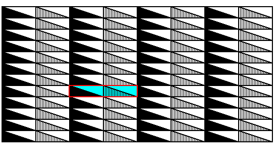
Figure 5. The antisymmetry pattern, as depicted in the bottom image of Figure 3, is in fact just a P1 pattern, which becomes clear when we take as unit mesh the one indicated in the present Figure. The pattern is just the result of an asymmetric motif being translated along two independent directions.
However, in order to express the striped nature of the pattern, we can call it the antisymmetry group P1 / P1 .

or

and

or

which means that we indicate the striped or checkerboard nature of the pattern. Interpreted as two-dimensional crystals we could think of two slightly different atomic complexes that alternate along one or another direction, or in both. An example of the latter possibility (alternation along two independent directions) could be an antisymmetry group derived from the group P1 by replacing the horizontal translation t by the antisymmetry transformation e1t , and the vertical translation T by the antisymmetry transformation e1T . We then get an alternation along two directions. See next Figure.
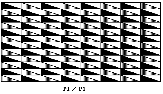
Figure 6. Antisymmetry ornament P1 / P1 derived from the pattern depicted as the top image of Figure 3 by replacing both generating translations by antisymmetry transformations. This implies that every odd number of translations (vertical or horizontal or both) is associated with a change from the existing value of the dual quality of the identity element to the other value of that quality (In the present case a change from a striped rectangular triangle to a solid black rectangular triangle). The result is a checkerboard-like pattern.
In the above Figure we see that the resulting subgroup (to which belongs the identity element) can be generated by repeating an asymmetric motif along two independent translations, in this case the translations t2 and T2 , which are elements of the full group. The structure of this subgroup is therefore isomorphic to P1 . See next Figure.
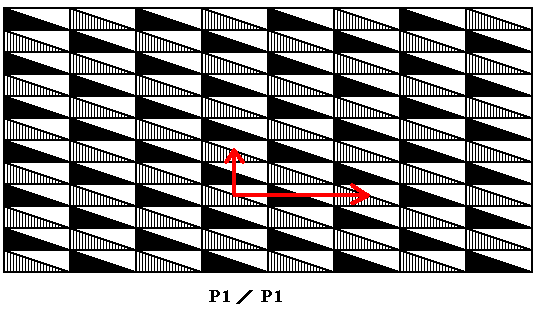
Figure 6.1. Generating translations t2 and T2 of the subgroup P1 of the antisymmetry group P1 / P1 of the previous Figure.
All the antisymmeties just discussed, i.e. the antisymmetry patterns derived from some initial P1 pattern, do not involve any desymmetrization (i.e. do not involve subgroups of lower symmetry) , because the initial pattern is already an ornament with lowest symmetry (while the subgroups that originate in antisymmetries are themselves always ornaments, like their full groups are).
Subgroups of P1
The next Figures show subgroups, and their corresponding patterns, of the plane group P1 , not associated with antisymmetry (and also not with colored symmetry). These subgroups result in stripes (line groups) or rosettes (point groups), and in this respect have lower symmetry than their full group, which is an ornament (plane group). So these subgroups do represent desymmetrizations of the corresponding full group.
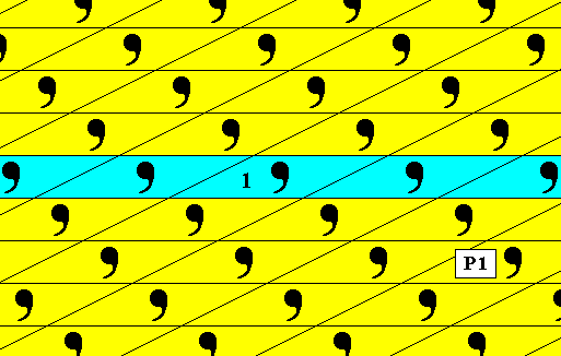
Figure 6a. The subgroup (blue) p11 (which is a line group represented by a frieze pattern) of the plane group P1 . This subgroup is not associated with antisymmetry and also not with colored symmetry. Its pattern can stand for a layer in a two-dimensional crystal The other parallel layers are cosets of this subgroup.
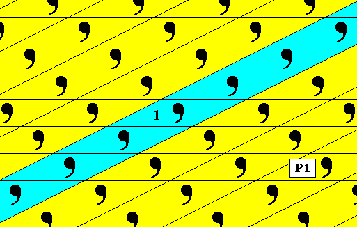
Figure 6b. The subgroup (blue) p11 (which is a line group represented by a frieze pattern) of the plane group P1 . Also this subgroup is not associated with antisymmetry and also not with colored symmetry. As in the previous case, its pattern can stand for a layer in a two-dimensional crystal. The other parallel layers are cosets of this subgroup.
Next we consider the plane group P2 .
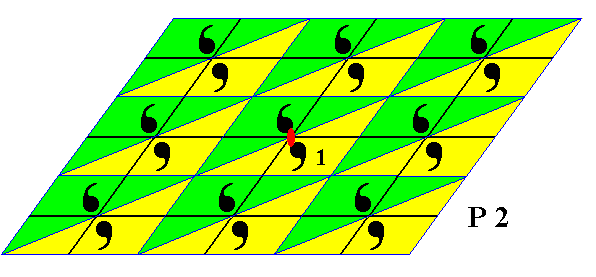
Figure 7. A pattern representing the plane group P2 . The triangular group elements are indicated. The colors do not (yet) represent (anti)symmetry features. One 2-fold rotation axis is indicated by a small solid red ellipse. The oblique lattice is indicated by black lines. One of the group elements is chosen to be the identity element 1 . The pattern must be imagined to be extended indefinitely over the plane.
Now we set the initial color of the motifs s.str. as being red, while the initial color of their background is set to be blue. See next Figure.
Figure 8. The P2 pattern of the previous Figure. The initial color of the motifs s.str. is set as being red, while that of their background as being blue. One 2-fold rotation axis is indicated by a small solid blue ellipse.
In order to derive an antisymmetry group, we replace the horizontal generating translation th by the antisymmetry transformation e1th , and the oblique translation to by the antisymmetry transformation e1to , where e1 will stand for the color permutation (Red Blue) (cycle notation). The resulting antisymmetry group P2 / P2 is shown in the next three Figures.
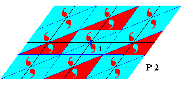
Figure 9. First phase of the derivation of the antisymmetry pattern from the P2 pattern of the previous Figure. From the identity element 1 we see four translations (two horizontal and two oblique translations), and these bring with them a color change according to the color permutation (Red Blue) . Even numbers of translations (whether they be th's or to's or both) will not result in a color change, while odd numbers do.
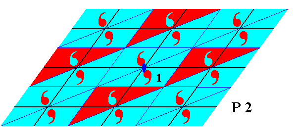
Figure 10. Second phase of the derivation of the antisymmetry pattern from the P2 pattern of Figure 8. The half-turn does not effect a color change (i.e. it is set as not to be replaced by an antisymmetry transformation), so the resulting element has the original colors. But when this element is translated a color change will occur in all cases where the number of translations is odd.
So the final result is a checkerboard pattern. See next Figure.
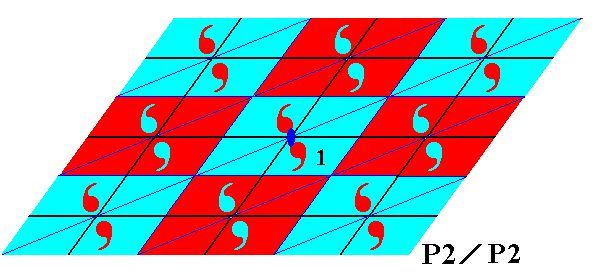
Figure 11. The antisymmetry group P2 / P2 derived from the symmetry group P2 (Figure 8).
As the next Figure shows, the blue elements, i.e. the elements represented by red commas and blue background, form a subgroup that is isomorphic to P2 , therefore the symbol for the antisymmetry group associated with this subgroup is P2 / P2 .
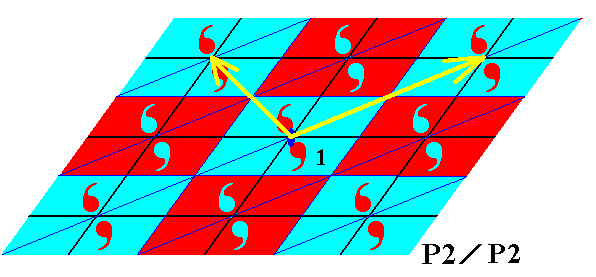
Figure 11a. Same pattern as in previous Figure. The set of blue elements is in fact a 2-fold rosette that is repeated by two translations along two independent directions (yellow arrows), and is therefore isomorphic to the group P2 . Each of the mentioned translations is itself a combination of oblique and horizontal translations of the full group (Therefore these translations -- yellow arrows -- also belong to the full group. If this were not so then the 'subgroup' would not be a subgroup of the full group at all).
In the above Figures we had the motifs s.str. (each consisting of two units relatated to each other by a half-turn) such as having their center at a lattice point. It is perhaps instructive to show the equivalent case of having the centers of these motifs wholly inside a lattice mesh. See next Figure.
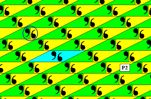
Figure 11b. Pattern according to the plane group P2 . The centers of its 2-fold motifs (one is highlighted by a circle) coincide with the mid-points of the lattice meshes. The colors green and yellow indicate the areas that can represent group elements, they do not indicate symmetry features. A unit mesh is indicated (blue).
In order to derive an antisymmetry pattern, we set the initial color of the motifs s.str. as being red, while that of their background as being blue. See next Figure.
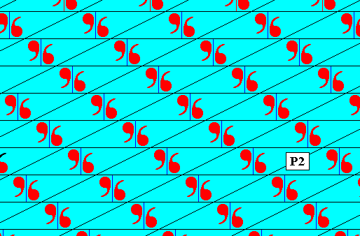
Figure 11c. The P2 pattern of the previous Figure. The color of the motifs s.str. is set to be red, while that of their background blue.
The next Figure shows the pattern of the antisymmetry group P2 / P2 derived from the pattern of the previous Figure. As in the above case, we have replaced the vertical and horizontal translations by corresponding antisymmetry transformations, while not replacing the half-turn.
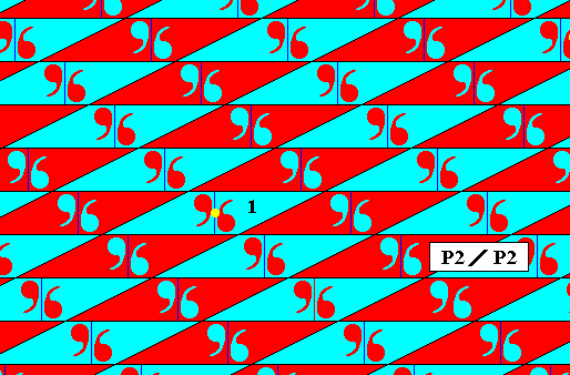
Figure 11d. Antisymmetry ornament derived from the P2 pattern of the previous Figure. The color swap is determined by the color permutation e1 = (Red Blue) (cycle notation). One area is chosen to represent the identity element 1 . The axis of the generating half-turn is indicated by a yellow dot.
The next Figure explains that the subgroup associated with the antisymmetry of the previous Figure is isomorphic to P2 .
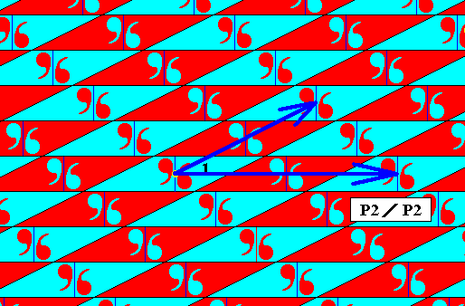
Figure 11e. If we look to the blue part of the above antisymmetry pattern (i.e. to the blue areas with red commas), we see that we can interpret it as a 2-fold rosette multiplied by two independent translations (which are themselves elements of the full group, because they each consist of a combination of generating translations of the full group). Therefore this subgroup has P2 symmetry, demanding the symbol of the corresponding antisymmetry group to be P2 / P2 .
The next Figures give the point lattices, respectively underlying a P2 pattern and the antisymmetry pattern that can be derived from it by the above prescription (both translations replaced by their corresponding antisymmetry transformations).
Figure 11f. Point lattice (indicated by blue connection lines) of a P2 pattern.
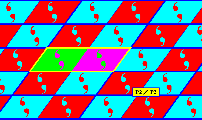
Figure 11g. Point lattice (indicated by strong blue connection lines) of the antisymmetry pattern derived from the P2 pattern of the previous Figure, by replacing both generating translations (horizontal translation, oblique translation) by their corresponding antisymmetry transformations, as (was also) done above. A unit mesh is indicated by a yellow outline and alternative colors.
Another antisymmetry group can be derived from the group P2 when we replace the half-turn h by the antisymmetry transformation e1h , while the two translations are not replaced. In order to see what happens, recall that the group P2 is generated from the initial element (identity element) as follows : The initial element -- as represented by a triangular area containing one asymmetric unit of the motif s.str. -- is subjected to the two generating translations over and over again, resulting in a pattern of generated triangular areas, covering half of the plane. The other half of the triangles are generated by subjecting the identity element (initial element) to the half-turn, the axis of which is indicated by a small solid ellipse in the previous Figures. The resulting element will now also be subjected to the repeated application of the two translations, resulting in the other half of the triangles, i.e. resulting in the missing triangles.
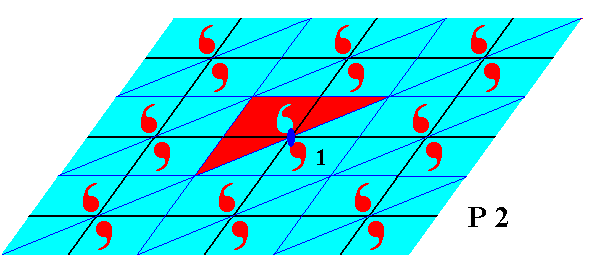
Figure 12. First phase of generating the antisymmetry group P2 / P1 from the generating symmetry group P2 of Figure 8. The element generated from the initial element by the half-turn (about the axis indicated by a solid ellipse) will change color as shown, because the transformation is in fact e1h .
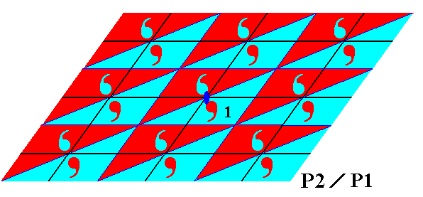
Figure 13. The element resulted from the half-turn, and having changed color according to the color permutation e1 = (Red Blue) (cycle notation), is translated horizontally and obliquely (and both). These translations by themselves do not effect any color change, but combined with e1h they do, meaning that the colors of the initial element 1 will be changed. The resulting group is the antisymmetry group P2 / P1 .
From the above Figure we can easily see that the blue elements (i.e. the elements represented by red commas and blue background) form a subgroup that is isomorphic to P1 , therefore the symbol for the resulting antisymmetry group (associated with this subgroup) is P2 / P1 .
The next Figure gives the point lattice underlying an antisymmetry pattern P2 / P1 , derived according to the above prescription (replacing the half-turn).
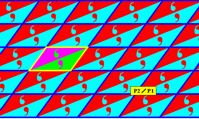
Figure 13a. Point lattice (indicated by dark blue connection lines) of an antisymmetry pattern P2 / P1 , derived from a P2 pattern according to the above prescription (half-turn replaced by the corresponding antisymmetry transformation). A unit mesh is indicated by yellow outline and alternative colors. Compare with the lattice of the generating P2 pattern, Figure 11f.
The next Figures give two more examples of the antisymmetry groups P2 / P2 and P2 / P1 , derived from the group P2 . We start from a motif taken from Neolithic ornamental art, and we construct the corresponding generating P2 pattern. From that pattern we will derive the two antisymmetry patterns, first the P2 / P2 pattern, and then the P2 / P1 pattern which (latter pattern) is present in Neolithic ornamental art.
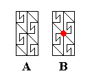
Figure 14. Generating C2 rosette, which will generate a P2 pattern. It is the unit mesh of that periodic pattern to be generated.
A : The C2 rosette.
B : The same rosette, with the 2-fold rotation axis indicated.
The rectangular outline signifies the boundary of the unit mesh.
The next Figure shows which lines belong to the pattern, and which lines belong only to the lattice connection lines.
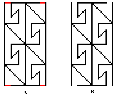
Figure 15. Magnification of the area of the unit mesh (of a P2 pattern to be generated) as depicted in the previous Figure.
A : The red line segments do not belong to the pattern proper, they belong to the lattice connection lines (which determine the boundaries of the unit mesh).
B : The motif proper. The whole rectangular area plus contents represent the motif s.l., while the lines represent the motif s.str.
The next Figure gives the periodic pattern (P2) resulting from the translational repetition of the motif s.str. (which is a C2 rosette) as given in B of Figure 20, but using a smaller version.
Figure 16. ( A smaller version of ) the two-fold rosette of Figure 20 (B) is multiplied by two translations along two independent directions. Because the motif has C2 symmetry, the resulting plane group is P2 , despite the fact that the lattice consists of rectangular meshes.
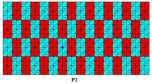
Figure 17. Motifs s.l. (red, blue) of the P2 pattern of the previous Figure. The colors (red, blue) do not signify any asymmetries, but only serve to highlight the motifs s.l. The axis of the generating half-turn is indicated by the dark blue dot (There are of course an infinity of such 2-fold axes. One of them is chosen as the generating half-turn. The rectangular area through which this axis goes, consists of two group elements, one of which is taken to be the identity element of the group).
If, however, the colors red and blue, of the above Figure DO represent symmetry features, then we have the antisymmetry group P2 / P2 , obtained by replacing the horizontal translation and the vertical translation by antisymmetry transformations, resulting in an alternating color change, according to the color permutation e1 = (Red Blue) . If the identity element of the generating group P2 is a 'blue' element (i.e. an element represented by a black motif s.str. plus blue background), then those (blue) elements form the subgroup P2 of the full group. The next Figure shows the lattice of this subgroup.
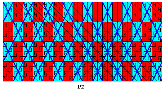
Figure 18. Lattice (thick blue lines) of the subgroup P2 (blue areas) of the full group P2 (red + blue areas), as depicted in the previous Figure.
Another antisymmetry group can be derived from the above pattern (Figure 16) by replacing the half-turn h (about the point indicated in Figure 17) of the generating symmetry group by the corresponding antisymmetry transformation e1h , while letting the translations not being replaced. The antisymmetry group P2 / P1 is then generated as follows :
Figure 19. Antisymmetry ornament P2 / P1 derived from the P2 pattern of Figure 16.
This particular ornament is present in Neolithic art.
(Adapted from JABLAN, 2002)
The next Figures explain the derivation of the just given antisymmetry group P2 / P1 .
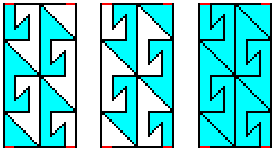
Figure 20.
Left image : (Initial) asymmetric group element, with respect to the pattern of Figure 16. This group element is represented by the blue part (plus corresponding black line segments) of the rectangular area.
Middle image : Asymmetric group element generated from the initial group element (left image) by a half-turn about the center of the rectangular area (The axis of this half-turn is perpendicular to that area).
Right image : The two group elements together (represented by the imposition of the left image upon the middle image) form a C2 rosette.
In the above Figure we see an excellent example of a complicated fundamental region, quite different from the rectangles or triangles we were used to.
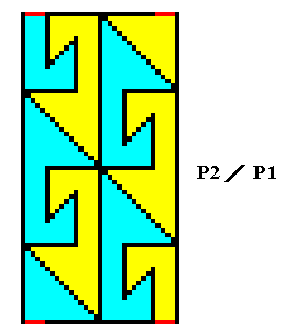
Figure 21. Two group elements of the antisymmetry ornament P2 / P1 of Figure 19 (Here the [areas representing the] elements enlarged and with different colors). As such they form the unit mesh of that antisymmetry group.
Subgroups of P2
The next Figures show subgroups (and their corresponding patterns) of the group P2 , not associated with antisymmetry or colored symmetry.
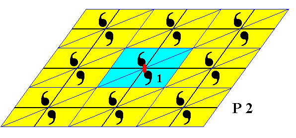
Figure 22. The subgroup (blue) C2 (which is a point group represented by a 2-fold rosette) of the plane group P2 .
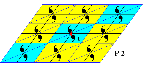
Figure 23. The subgroup p12 (which is a line group represented by a frieze) of the group P2 . Its pattern can represent a layer in a 2-dimensional crystal. The other parallel layers represent cosets of this subgroup.
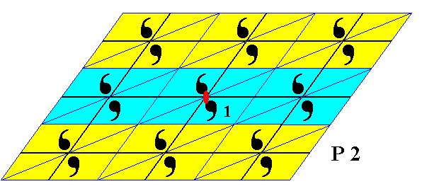
Figure 24. The subgroup p12 (which is a line group represented by a frieze) of the group P2 . Its pattern can also represent a layer in a 2-dimensional crystal. As in the previous case, the other parallel layers represent cosets, i.e. cosets of the present subgroup.
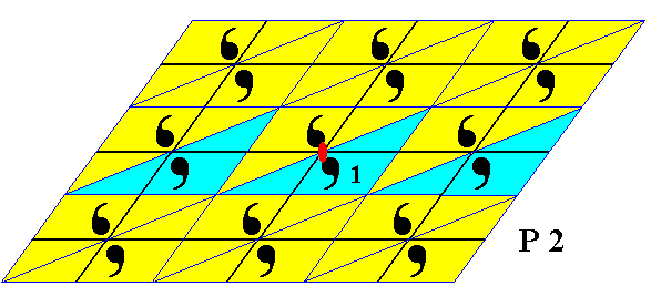
Figure 25. The subgroup p11 (which is a line group represented by a frieze) of the group P2 . This subgroup is also a subgroup of the subgroup P12 depicted in the previous Figure. Its pattern can represent a layer in a 2-dimensional crystal. The other parallel layers represent cosets of this subgroup (p11).
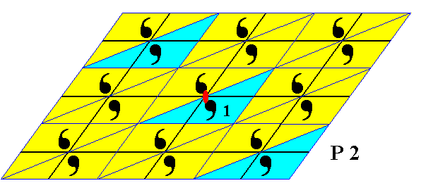
Figure 26. Subgroup p11 (which is a line group represented by a frieze pattern) of the group P2 . The subgroup can be generated by the combination of the horizontal and oblique translations. Also this subgroup can represent a layer in a two-dimensional crystal. The other parallel layers are cosets of this subgroup.
In the next document we will continue with the study of the plane group patterns with respect to their possible antisymmetries and their subgroups.
e-mail : 
To continue click HERE for further group theoretic preparation to the study of the structure of three-dimensional crystals (crystallography) and the basic symmetry of organisms (promorphology)
Back to 3-dimensional crystals (conclusion), Organic Tectology and Promorphology
Back to subpatterns and subgroups (introduction)
Back to subpatterns and subgroups Part II
Back to subpatterns and subgroups Part III
Back to subpatterns and subgroups Part IV
Back to subpatterns and subgroups Part V
Back to subpatterns and subgroups Part VI
Back to subpatterns and subgroups Part VII
Back to subpatterns and subgroups Part VIII
Back to subpatterns and subgroups Part IX
Back to subpatterns and subgroups Part X