
e-mail :

Sequel to Group Theory
We'll start with reminding the reader about the "Important Remark" near the end of Part III of Group Theory (To see it, click HERE and then go to (end of) Part III ), a Remark concerning the direction of reading products of group elements, like, say, apq. We read such products (from that Remark onwards) from back to front. Thus (with respect to apq) first q, then p, and then a.
Infinite two-dimensional periodic patterns, or Ornaments (sequel)
Now we're going to consider the plane group Pm with respect to subgroups and antisymmetry.
Figure 1. A pattern according to the plane group Pm .
The areas representing group elements are indicated by the (smallest) rectangles. One such element is chosen to represent the identity element 1 . The initial colors are set to be red for the motifs s.str., while that of their background is set to be blue.
An antisymmetry group can be derived from the group Pm by replacing the vertical translation tv by the antisymmetry transformation e1tv , where we let e1 be the color permutation (Red Blue) (cycle notation). The other generators will not be replaced. This effects a vertical alternation of the colors red and blue, because
tv ==> e1tv .
tv2 ==> e1tve1tv = e12 tv2 = tv2 .
tv3 = tvtv2 ==> e1tvtv2 = e1tv3 .
etc.
The next Figure depicts the resulting Pm / Pm antisymmetry pattern.
Figure 2. Antisymmetry group Pm / Pm derived from the symmetry group Pm as depicted in Figure 1. In this derivation the vertical translation tv is replaced by the antisymmetry transformation e1tv , where e1 is the color permutation (Red Blue) . The reflection line of the generating reflection is indicated by m .
In the above Figure we can see that the blue part of the Figure is in fact a repetition of a symmetric unit according to two translations along two independent directions. Therefore this blue part is a subgroup (of the full group Pm ) with structure Pm , and the symbol for the antisymmetry group associated with this subgroup is Pm / Pm .
The next Figures give the respective point lattices of the generating Pm pattern and of the above derived antisymmetry pattern.
Figure 2a. Point lattice (indicated by connection lines) of the generating Pm pattern.
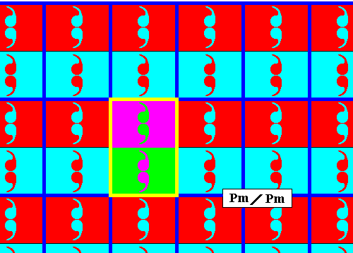
Figure 2b. Point lattice (indicated by strong blue connection lines) of the above derived antisymmetry pattern (Figure 2). A unit mesh is indicated by yellow outline and alternative colors.
Another antisymmetry ornament can be obtained from the Pm pattern of Figure 1 by replacing the horizontal generating translation by the corresponding antisymmetry transformation, while the other generators are not replaced. The next Figure shows the result.
Figure 3. Antisymmetry ornament derived from the pattern of Figure 1 by replacing the horizontal translation by the corresponding antisymmetry transformation.
The next Figure gives the point lattice of the just derived antisymmetry pattern.
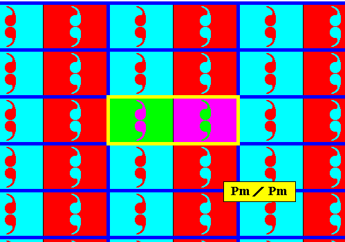
Figure 3a. Point lattice (indicated by strong blue connection lines) of the above derived antisymmetry pattern. A unit mesh is indicated by yellow outline and alternative colors. Compare with the lattice of the generating Pm pattern depicted in Figure 2a.
Yet another antisymmetry pattern can be obtained from the Pm pattern of Figure 1 by replacing the reflection m by the corresponding antisymmetry transformation, while the other generators not being replaced. The next Figure gives the result.
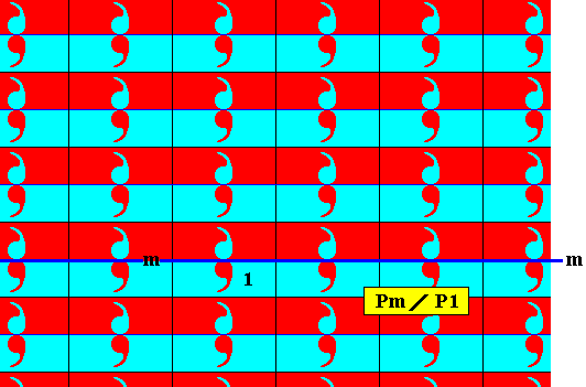
Figure 4. Antisymmetry ornament derived from the pattern of Figure 1 by replacing the reflection in the line m by the corresponding antisymmetry transformation.
As can be seen in the above Figure, the set of 'blue' elements (containing the identity element) is a subgroup of the full group, a subgroup with the structure P1 . Therefore the symbol for the corresponding antisymmetry group must read Pm / P1 .
The next Figure gives the point lattice of the just derived antisymmetry pattern.
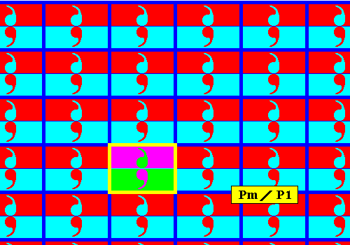
Figure 4a. Point lattice (indicated by strong blue connection lines) of the above derived antisymmetry pattern. A unit mesh is indicated by yellow outline and alternative colors. Compare with the lattice of the generating Pm pattern depicted in Figure 2a.
And indeed, we can derive yet another antisymmetry pattern from the Pm pattern of Figure 1 by replacing the vertical generating translation and the generating reflection (in the line m ) by their corresponding antisymmetry transformations. The next Figure gives the result.
Figure 5. Antisymmetry ornament derived from the pattern of Figure 1 by replacing the generating reflection in the line m and the vertical generating translation by the corresponding antisymmetry transformations.
Let us explain how we obtained the antisymmetry pattern of the previous Figure. In order to do so, in the next Figure we give the proper identities of a number of group elements in the column where the identity element (initial element) 1 is situated. To derive the antisymmetry group, as is done in the above Figure, the reflection m is being replaced by the antisymmetry transformation e1m , while the vertical translation (let us call it) t is being replaced by the antisymmetry transformation e1t . The horizontal translation (let us call it T ) is not replaced. So the generator set of the antisymmetry group is {e1m, e1t, T }. Combining these elements (which are transformations) will result in the remaining group elements (of which, of course, there is an infinity). And, wherever an odd number of e1's occur in a group element symbol, the colors of the area-and-content representing that group element, must become the swapped version of the colors of the identity element, i.e. with respect to the colors that figure in the identity element (red comma, blue background) that new element must have its colors swapped (blue comma, red background). See next Figure.
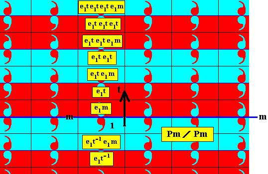
Figure 6. Antisymmetry pattern of Figure 5. Some group elements in the column where the identity element is situated are explicitly identified by group element symbols, expressing the transformations in terms of the generators e1m (reflection in the line m followed by color swap), e1t (vertical translation followed by a color swap), and T (horizontal translation, but this transformation does not occur in the mentioned column). The vertical translation is indicated by a black arrow. Because the horizontal translation is neutral with respect to color change, no such change occurs along the horizontal direction. So if we go to the right or to the left, starting from an element with an odd number of e1's , that number stays odd. The same with respect to even numbers.
In the Figures 5 and 6 one can see that the set of 'blue' elements, i.e. the elements represented by an area that has a red comma and a blue background (a set of elements containing the identity element of the group), is a D1 rosette-that-is-repeated-by-two-independent-translations, which as transformations are also elements of the full group. So this set of blue elements forms a subgroup Pm of the full group. Therefore the symbol for the corresponding antisymmetry group must be Pm / Pm See next Figure.
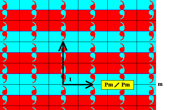
Figure 7. The set of blue elements of the group Pm / Pm forms a subgroup with Pm symmetry.
The next two Figures give the point lattice of the just derived antisymmetry pattern.
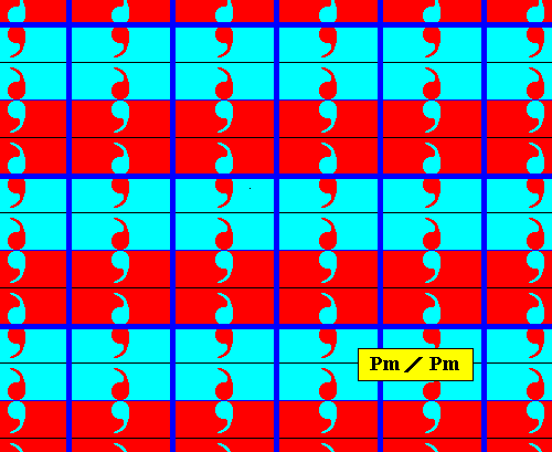
Figure 7a. Point lattice (indicated by strong blue connection lines) of the above derived antisymmetry pattern (Figure 5). Compare with the lattice of the generating Pm pattern depicted in Figure 2a.
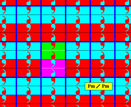
Figure 7b. Point lattice (indicated by strong blue connection lines) of the above derived antisymmetry pattern (Figure 5). A unit mesh is indicated by alternative colors.
In all the above cases of antisymmetry patterns we obtain striped patterns.
Finally, we can derive an antisymmetry pattern from the Pm pattern of Figure 1 by replacing all three generators -- reflection, horizontal translation, vertical translation -- by their corresponding antisymmetry transformations. The next Figure gives the result.
Figure 8. Antisymmetry pattern Pm / Cm derived from the Pm pattern of Figure 1 by replacing all three generators (reflection and two translations) by their corresponding antisymmetry transformations. The result is a checkerboard-like pattern.
The set of 'blue' elements in the above Figure forms a subgroup with Cm symmetry, which means that its pattern is based on a rhombic lattice (or, equivalently, on a centered rectangular lattice). The next Figure shows the rhombic outline of a possible unit mesh of the rhombic lattice underlying the pattern representing the subgroup Cm .
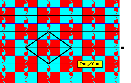
Figure 9. Outline of the rhombic unit mesh of the rhombic lattice underlying the subgroup Cm of the antisymmetry group Pm / Cm .
For this subgroup we can also detect a centered rectangular unit mesh :
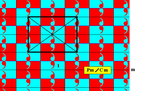
Figure 10. Outline of the centered rectangular unit mesh of the centered rectangular lattice underlying the subgroup Cm of the antisymmetry group Pm / Cm .
The next Figure gives a better image of the subgroup Cm associated with the above antisymmetry group, after having erased the elements not belonging to this subgroup.
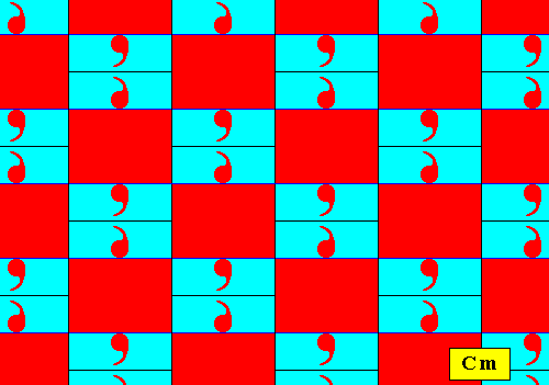
Figure 11. Pattern according to the subgroup, as it emerged during the derivation of the antisymmetry group Pm / Cm (Figure 8).
The rhombic lattice underlying the pattern of the subgroup found above, is depicted in the following Figure.
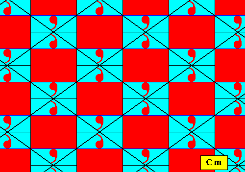
Figure 12. Rhombic lattice underlying the subgroup Cm found above. At each lattice point we find a motif s.str. consisting of two units that relate to each other by a reflection.
The position of the rhombic lattice can equivalently chosen to be different, namely such that in the center of each rhombic mesh there is a motif s.str. consisting of two units, while at the mesh's corners there are no such motifs. See next Figure.
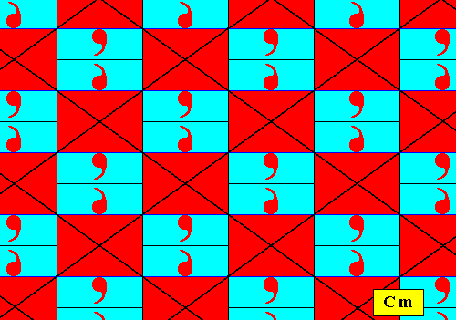
Figure 13. Rhombic lattice underlying the subgroup Cm found above. At the center of each lattice mesh we find a motif s.str. consisting of two units that relate to each other by a reflection.
In the next Figure we show the same pattern as in the above Figure, but now with all the auxiliary lines erased, except for the lines that outline the rhombic lattice (i.e. the lines connecting the points of the rhombic point lattice).
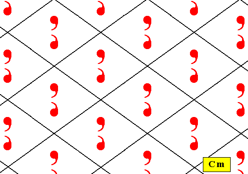
Figure 14. The pattern representing the subgroup (Cm) found above, with its rhombic lattice.
In the above Figure we can easily verify that the subgroup has indeed Cm symmetry, therefore the antisymmetry group ( Figure 8 ) associated with this subgroup must be denoted by Pm / Cm .
The next Figures illustrate the point lattice of the above derived antisymmetry pattern ( Figure 8 ).
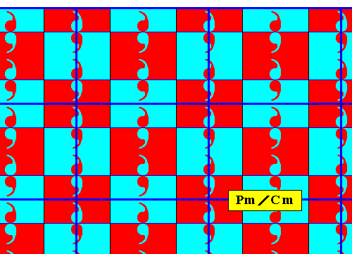
Figure 14a. Point lattice (indicated by dark blue connection lines) of the above derived antisymmetry pattern ( Figure 8 ). The lattice is here given as a c e n t e r e d r e c t a n g u l a r l a t t i c e .
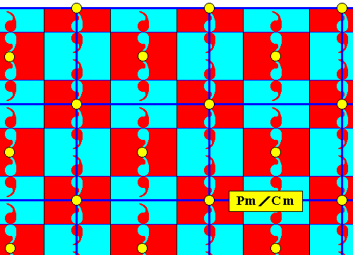
Figure 14b. The equivalent points of the point lattice, as given in the previous Figure, are highlighted to show the centered rectangular nature of the lattice.
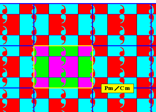
Figure 14c. A unit mesh of the above centered rectangular lattice is indicated by yellow outline and alternative colors. Compare with the lattice of the generating Pm pattern depicted in Figure 2a.
The next three Figures indicate an alternative (and equivalent) choice of lattice, viz. a rhombic lattice, of the same antisymmetry pattern.
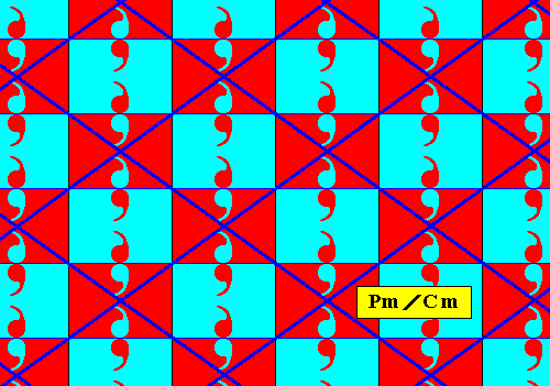
Figure 14d. Rhombic point lattice (indicated by dark blue connection lines) of the above derived antisymmetry pattern Pm / Cm .
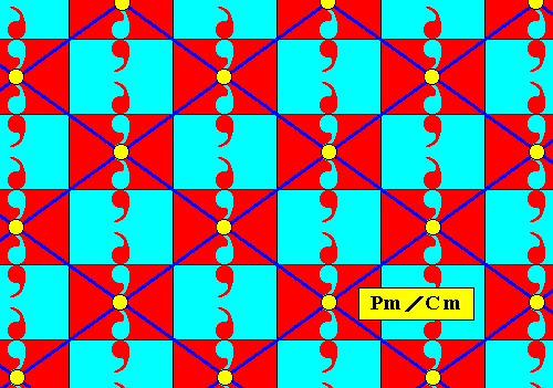
Figure 14e. Rhombic point lattice (indicated by dark blue connection lines) of the above derived antisymmetry pattern Pm / Cm . The equivalent lattice points are highlighted.
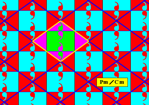
Figure 14f. Rhombic point lattice (indicated by dark blue connection lines) of the above derived antisymmetry pattern Pm / Cm . A unit mesh is indicated by yellow outline and alternative colors.
The next Figure gives an example of the group Pm from the Neolithic art of the Middle East. We will first analyze this pattern, and then derive an antisymmetry pattern from it.
Figure 15. Ornament with the symmetry group Pm in the Neolithic art of the Middle East (Hacilar, Tell el Hallaf, around 6000 B.C.).
(Adapted from JABLAN, 2002)
The next Figure outlines the motifs s.l. of the pattern of Figure 15.
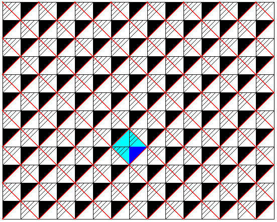
Figure 16. The Pm pattern of the previous Figure. The red lines indicate the (boundaries of the) motifs s.l. . These motifs clearly have D1 symmetry (i.e. their only symmetry element is a mirror line). One such motif is highlighted. It can be chosen as unit mesh, which implies that the red lines also signify the lattice which underlies the pattern. As representing a plane group the pattern must be imagined to be extended indefinitely over the plane.
The red lines in the above Figure can be seen as lattice connection lines, i.e. as lines that connect the nodes of the point lattice. This lattice thus consists of square meshes. An equivalent lattice can be imagined when we connect the centers of the motifs s.l. with each other. And this (alternative) lattice then describes the repetition of the motifs s.l. But, because it is equivalent to the lattice established earlier (red lines in the above Figure), this earlier lattice also describes the (way of) repetition of the motifs s.l.
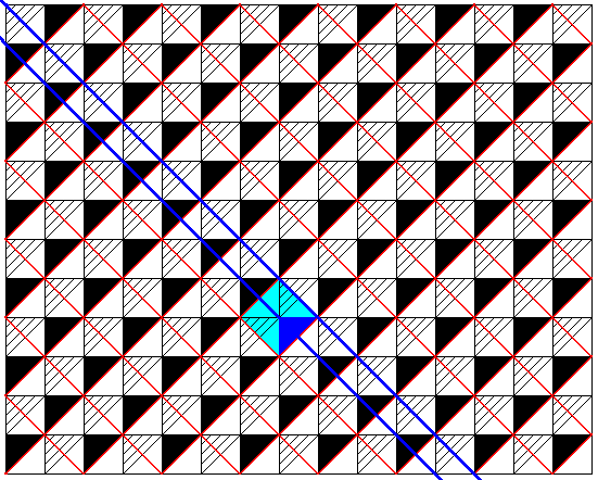
Figure 17. Some mirror lines are indicated in the Pm pattern of the previous Figures.
The next Figure shows that the lattice meshes are primitive, i.e. that their mid-points are not equivalent to their corner-points.
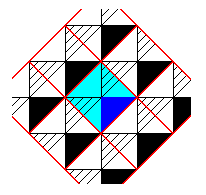
Figure 18. Unit mesh (blue) of the periodic pattern of the previous Figures. The mid-point of this unit mesh (unit cell) is not equivalent to its corner-points. So the mesh is primitive.
Our pattern does not have rotation axes, but only mirror lines. Its unit mesh is primitive. So it must represent the plane group Pm .
We will now derive from this Pm ornament an antisymmetry ornament. The next Figure shows that a motif s.l. consists of two group elements, i.e. it consists of two asymmetric areas (plus content) representing group elements.
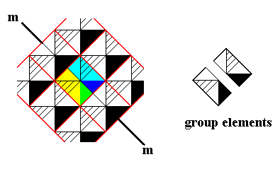
Figure 19. A motif s.l. (which also embodies a unit mesh) consists of two asymmetric figures related to each other by reflection (m), and representing group elements.
For our antisymmetry ornament to be derived we replace the generating reflection m by the antisymmetry transformation e1m , where the antiidentity transformation e1 is defined in the following Figure :
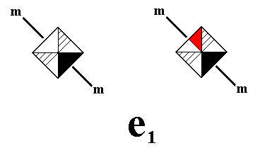
Figure 20. Definition of the antiidentity transformation e1 , where e1 will stand for the permutation of the two images, i.e. these images will be the two 'values' of a dual quality. This dual quality is : "either the left image, or the right image" . More precisely, it is the color permutation (Red White) (cycle notation) applied to the upper non-striped part of a group element (as defined in Figure 19).
We will now derive the antisymmetry ornament, as defined above, in two phases. See next Figures.
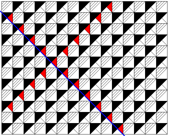
Figure 21. First phase of the derivation of an antisymmetry ornament from the ornament of Figure 15. The generating reflection line is indicated by a dark blue solid line. The reflection of the initial group element is in fact the antisymmetry transformation e1m , where e1 is the antiidentity transformation as defined above. So the element e1m contains a red triangle. The generating translations (in two perpendicular diagonal directions) do not contribute to any further color swap. Also the combinations of those translations do not so contribute. The next Figure shows the completion of the derivation.
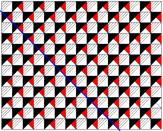
Figure 22. Completion of the derivation of the antisymmetry pattern -- as defined above -- from the pattern of Figure 15.
The next Figure highlights the initial group element.
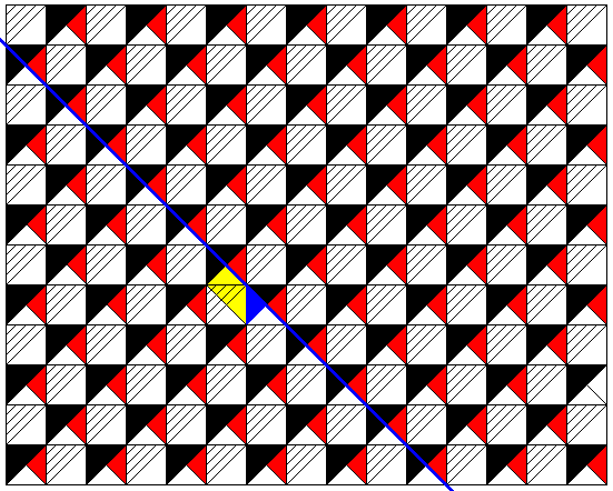
Figure 23. In the antisymmetry pattern of the previous Figure the initial group element is indicated.
The next Figure shows that the subgroup associated with this antisymmetry group (and which, of course, contains the identity element) is isomorphic to the plane group P1 , because we see an asymmetric motif being translated along two independent directions. And these translations are also elements of the full group (which should be so, if it is to be a subgroup of the full group). Therefore the symbol for the antisymmetry group associated with this subgroup is Pm / P1 .
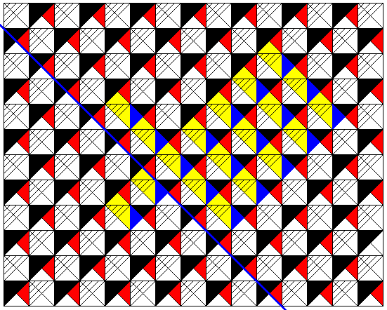
Figure 24. The Figure indicates that the subgroup associated with the derived antisymmetry group is isomorphic to the group P1 .
In the next document we will give some examples of subgroups of Pm ornaments, subgroups not associated with antisymmetry or colored symmetry, and will dwell a while on pondering about the ontological status of symmetry groups, before we continue our study of antisymmetry and subgroups of the other plane group patterns.
e-mail : 
To continue click HERE for further group theoretic preparation to the study of the structure of three-dimensional crystals (crystallography) and the basic symmetry of organisms (promorphology)
Back to 3-dimensional crystals (conclusion), Organic Tectology and Promorphology
Back to subpatterns and subgroups (introduction)
Back to subpatterns and subgroups Part II
Back to subpatterns and subgroups Part III
Back to subpatterns and subgroups Part IV
Back to subpatterns and subgroups Part V
Back to subpatterns and subgroups Part VI
Back to subpatterns and subgroups Part VII
Back to subpatterns and subgroups Part VIII
Back to subpatterns and subgroups Part IX
Back to subpatterns and subgroups Part X
Back to subpatterns and subgroups Part XI