
e-mail :

Sequel to Group Theory
We'll start with reminding the reader about the "Important Remark" near the end of Part III of Group Theory (To see it, click HERE and then go to (end of) Part III ), a Remark concerning the direction of reading products of group elements, like, say, apq. We read such products (from that Remark onwards) from back to front. Thus (with respect to apq) first q, then p, and then a.
Infinite two-dimensional periodic patterns, or Ornaments (sequel)
In the previous document we considered the plane group P2mm with respect to the antisymmetry groups that can be derived from it. Here we will give an example of such an antisymmetry pattern from Neolithic art. Then we will discuss some subgroups (represented as subpatterns) of the group P2mm , and, finally, continue our investigation (about antisymmetry and subgroups) with respect to the remaining plane groups.
The present document is wholly devoted to the just mentiond example from Neolithic art (Figure 32 ). Its analysis is instructive for an understanding and application of antisymmetry in plane patterns.
Figure 1. A P2mm pattern, which could perhaps figure as the generating symmetry group of the mentioned antisymmetry group, found in Neolithic art [ In fact, as we will see, it cannot so figure : The generating pattern must already be dichromatic (i.e. already consisting of two colors or their analogues), which means that the antiidentity transformation e1 cannot signify just a swap between two colors, but must be a swap between two color c o n f i g u r a t i o n s -- X and Y -- that transform into each other. And as such it must then be combined with one of the symmetry transformations of the initial pattern].
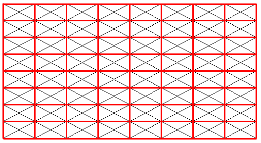
Figure 2. For the P2mm pattern of the previous Figure we have inserted the rectangular point lattice (shown by connection lines [red] ) that describes the periodic repetition of motifs. The oblique lines belong to the motif s.str.
From the above P2mm pattern we will try to derive an antisymmetry pattern by replacing both generating translations (horizontal and vertical) by their corresponding antisymmetry transformations. Let us first depict the areas representing group elements :
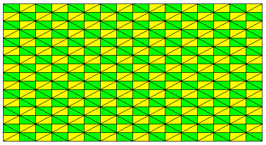
Figure 3. (Rectangular) areas (green, yellow) representing group elements of the pattern of Figure 1. The colors do not signify symmetry features.
The next Figure shows the unit mesh and its content.
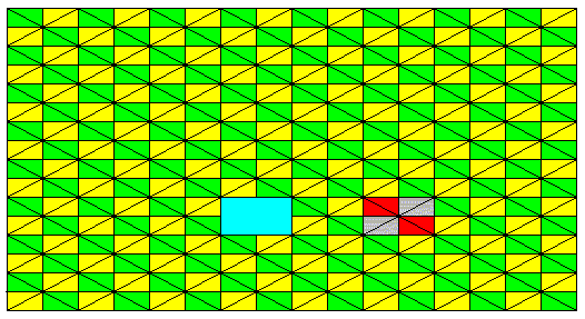
Figure 4. Same as previous Figure (P2mm pattern). A unit mesh is indicated (blue). At the right another such mesh is indicated together with its content : four areas representing group elements. A unit mesh consists of a D2 motif. And the pattern is built up by a periodic repetition of this motif in two perpendicular directions. So the pattern has indeed P2mm structure. Such a D2 motif is itself -- if containing the identity element -- a subgroup of the full group, and this subgroup has four group elements. The next Figure isolates such a D2 motif.
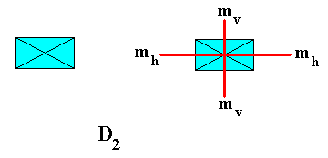
Figure 5. The D2 rosette of the pattern of Figure 1. Its two reflection lines are indicated. There is a 2-fold rotation axis going through the intersection point of the reflection lines.
The next Figure elaborates further on the D2 rosette figuring in our pattern.
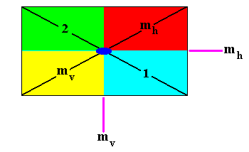
Figure 5a. Enlargement of the above D2 rosette. The black lines make up the motif s.str.
The symmetry of this rosette forms a dihedral group with four elements represented by the areas indicated:
The identity element 1 .
Reflection in the horizontal line mh .
Reflection in the vertical line mv .
Half-turn 2 about the intersection point of the two reflection lines (graphically indicated by a small solid ellipse).
To summarize and systematize :
The four symmetry elements (i.e. the geometric lines or axes to which the symmetries refer) are :
mh .
1 (blue).
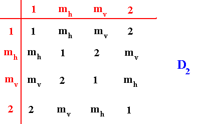
The next group table shows how the above given group elements combine to form the group D2 (where combining means consecutive execution of two symmetry transformations) :
For the antisymmetry pattern to be derived from the P2mm pattern, we set the initial color to be blue (in the context of a first trial). Both translations are replaced by the corresponding antisymmetry transformation where the antiidentity transformation e1 is the color permutation (Blue Red) (cycle notation). But first see next Figure.
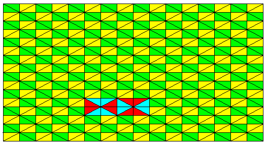
Figure 6. Indication of an antisymmetry pattern to be derived from the above P2mm pattern. With this we anticipate to construct an antisymmetry pattern as it is found in Neolithic ornamental art, and depicted in Figure 32.
While intending to derive an antisymmetry pattern from our initial P2mm pattern (Figure 1) along the lines indicated in Figure 6, we see that the areas representing group elements already contain two colors, i.e. such an area contains both colors of the permutation (depicted as the permutation (Red Blue) (cycle notation)). This means that the pattern representing the generating symmetry group must already be dichromatic, i.e. it must contain already two colors. The antisymmetry then must consist of changing that color configuration into another. So let's set up this alternative antisymmetry-generating P2mm pattern. See next Figure.
Figure 7. Alternative pattern representing the generating symmetry group P2mm . A certain initial color configuration is given, as indicated. A unit mesh is outlined.

Figure 8. The color configuration of an area representing a group element (and being part of a D2 rosette) is changed by the antisymmetry transformation e1th , where th is the horizontal generating translation, and where e1 is the permutation between two such configurations in the sense of the permutation (configuration X configuration Y) (cycle notation). The period of this permutation is therefore 2. And if it is associated with a generating translation, an alternation of these two color configurations will be the result.
The next Figure gives this same configuration change using the true final colors.

Figure 8a.
A : The color configuration change (X Y) of the previous Figure in true colors. This color configuration change is here (and also in the previous Figure) shown (only) with respect to one group element, viz. the one in the upper right of a unit mesh. We see that the red half of that element becomes blue, while the blue half becomes red.
B : The new motif is indicated, resulting when the just defined color configuration change is performed on all four group elements of the mesh.
C : If the color configuration change is again applied (which means that it is now two times applied to the initial motif, first X ==> Y and then Y ==> X ) , we get our initial motif back. So in the final antisymmetry pattern we can expect such alternations in the vertical as well as in the horizontal directions.
In fact, what we have done is e1the1th = (th)2 because e1 commutes with every symmetry transformation of the group, and (e1)2 = 1 , where e1 is the color configuration permutation (X Y) (cycle notation).
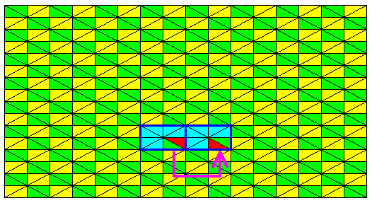
Figure 9. The second element of the same D2 rosette changes its color configuration under the same antisymmetry transformation as in the previous two Figures.

Figure 10. The third element of the same D2 rosette changes its color configuration under the same antisymmetry transformation as in the previous Figures.
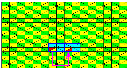
Figure 11. The fourth and last element of the same D2 rosette changes its color configuration under the same antisymmetry transformation as in the previous Figures.
In the same way we'll let the antisymmetry transformations do their job with respect to the vertical generating translation. See next Figures.
Figure 12. The first element of the same D2 rosette changes its color configuration under the antisymmetry transformation e1tv associated with the vertical generating translation tv , and where the antiidentity transformation e1 is a permutation of color configuration identical to the one that was associated with the horizontal generating translation, which was depicted above (See Figure 8).

Figure 13. The second element of the same D2 rosette changes its color configuration under the same antisymmetry transformation as in the previous Figure.
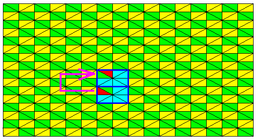
Figure 14. The third element of the same D2 rosette changes its color configuration under the same antisymmetry transformation as in the previous Figures.

Figure 15. The fourth and last element of the same D2 rosette changes its color configuration under the same antisymmetry transformation as in the previous Figures.
With the last image we will demonstrate the alternation that will emerge after repeated application of an antisymmetry transformation. The antisymmetry transformation as applied in Figure 15 was e1tv . When we apply this transformation repeatedly in both directions (up and down) we get :
e1tv-1e1tv-1e1tv-1 = e13 tv-3 = e1tv-3 .
e1tv-1e1tv-1 = e12 tv-2 = tv-2 .
e1tv = e1tv .
e1tve1tv = e12 tv2 = tv2 .
e1tve1tve1tv = e13 tv3 = e1tv3 .
etc.
Where an e1 appears, there we will have the corresponding color configuration swap with respect to the initial color configuration (as we find it in the [area representing the] identity element). And, as the above calculations show, an alternation will result in the vertical direction of the pattern (The same goes for the horizontal direction). The next Figure shows this alternation.
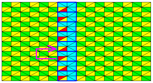
Figure 16. Alternation in the color configurations in a vertical row of (areas representing) group elements of the P2mm pattern of Figure 7 , representing the initial pattern. The remaining group elements are given by green and yellow colors (not signifying symmetry features). The identity element (initial element in the construction of the antisymmetry pattern) is set to be there where the arrow begins.
The next Figure highlights this alternation still further, foreshadowing the color configurations of the other group elements of that column.

Figure 17. Anticipation of the final antisymmetry result of a column of motifs.
In addition to the translations tv and th the initial symmetry pattern as given in Figure 7, has, as two more generators, two reflections, viz. a horizontal generating reflection m1 and a vertical generating reflection m2 . The initial pattern is then generated (see next two Figures) by applying, to the area representing the identity element, the vertical reflection m2 , then, to the result, the horizontal reflection m1 (which is equivalent to the application of m1m2 to the area representing the identity element [which in turn is identical to the application of a half-turn to the area representing te identity element]), then applying to this result the vertical reflection m2 (which is equivalent to applying m1 to the area representing the identity element).

Figure 17a. Generated D2 rosette, that will be repeated to give the initial periodic pattern (which is the antisymmetry-generating pattern). The areas generated by applying the generators m2 and m1 are named according to the corresponding group elements.
When we now subject this rosette to the vertical translation tv , and to the horizontal translation th , we end up with our initial pattern, i.e. the antisymmetry-generating pattern, as given in Figure 7 (from which we can derive the antisymmetry pattern, given in Figure 18, by the above given specifications).
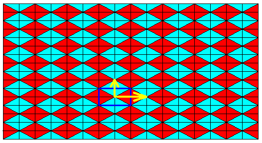
Figure 17b. Subjecting the D2 rosette to the two generating translations, tv (vertical translation) and th (horizontal translation), results in the initial pattern of Figure 7.
So the set of generators for this initial pattern (generating group) is here set to be :
From these generator elements all other group elements of the group describing our initial pattern (antisymmetry-generating pattern) can be generated (One could also choose a different set of generator elements, for example two horizontal reflections and two vertical reflections). Because the group is infinite we cannot give all its elements explicitly, but can give several : The four elements of the above generated D2 rosette are translated in the vertical (up-down) and horizontal (right-left) directions. So we get, among others, the following group elements of the initial pattern :
th-2 , th-1 , 1, th , th2 , th3 ,
th-2m2 , th-1m2 , m2, thm2 , th2m2 , th3m2 ,
th-2m1m2 , th-1m1m2 , m1m2, thm1m2 , th2m1m2 , th3m1m2 ,
th-2m1 , th-1m1 , m1, thm1 , th2m1 , th3m1 , etc.
tv-2 , tv-1 , 1, tv , tv2 , tv3 ,
tv-2m2 , tv-1m2 , m2, tvm2 , tv2m2 , tv3m2 ,
tv-2m1m2 , tv-1m1m2 , m1m2, tvm1m2 , tv2m1m2 , tv3m1m2 ,
tv-2m1 , tv-1m1 , m1, tvm1 , tv2m1 , tv3m1 , etc.
We will now construct the corresponding antisymmetry pattern, derived from the P2mm pattern of Figure 7, by replacing th by the antisymmetry transformation e1th and tv by the antisymmetry transformation e1tv .
The above group elements, i.e. the above given group elements of the initial pattern (antisymmetry-generating pattern), will now become :
th-2 , e1th-1 , 1, e1th , th2 , e1th3 ,
th-2m2 , e1th-1m2 , m2, e1thm2 , th2m2 , e1th3m2 ,
th-2m1m2 , e1th-1m1m2 , m1m2, e1thm1m2 , th2m1m2 , e1th3m1m2 ,
th-2m1 , e1th-1m1 , m1, e1thm1 , th2m1 , e1th3m1 , etc.
tv-2 , e1tv-1 , 1, e1tv , tv2 , e1tv3 ,
tv-2m2 , e1tv-1m2 , m2, e1tvm2 , tv2m2 , e1tv3m2 ,
tv-2m1m2 , e1tv-1m1m2 , m1m2, e1tvm1m2 , tv2m1m2 , e1tv3m1m2 ,
tv-2m1 , e1tv-1m1 , m1, e1tvm1 , tv2m1 , e1tv3m1 , etc.
Where the antiidentity transformation e1 is as defined above, viz. the permutation of two color configurations.
The next Figures develop the antisymmetry pattern step by step, and highlight the alternative color configuration change in one (arbitrarily chosen) column and in one (arbitrarily chosen) row of meshes. The initial mesh is highlighted by a blue contour line.
In line with Figure 17a we let the identity element 1 be represented by the bottom-left rectangle within the initial mesh, the m2 element be represented by the bottom-right rectangle of that same mesh, the m1m2 element by the top-right rectangle, and the m1 element by the top-left rectangle.
We will first show the alternating color configurations originating from the identity element as they occur in the (context of) the initial pattern as depicted in Figure 7 :
Figure 17b1. Indication of the color configuration change by repeatedly applying the antisymmetry transformations e1tv and e1th to the (area representing the) identity element (bottom left in the unit mesh : this identity element consists of two triangles). If we go along the column and look to equivalent (triangular) areas, we see an alternation of yellow (standing for red) and green (standing for blue). The same is the case when we go along the row.
In order to explain, let us isolate the column and row associated with the identity element. The isolation is indicated in the following Figure, and executed in the Figure next to the latter.
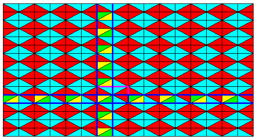
Figure 17b2. The column and row associated with the (area representing the) identity element will be isolated as indicated.
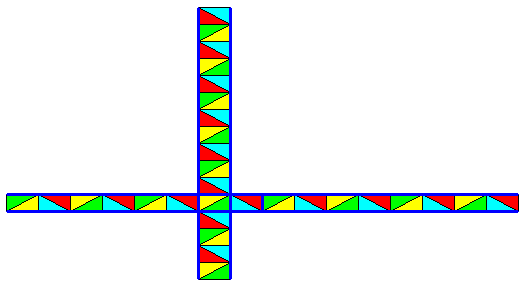
Figure 17b3. Isolated column and row associated with the identity element.
If we now restore yellow to red and green to blue, and omit the areas that are not involved in the horizontal and vertical antisymmetry translations when applied to the identity element, we get the following :
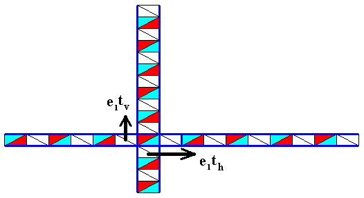
Figure 17b4. In this image we clearly see the alternating effect of the repeated application of the antisymmetry translations e1tv and e1th to the area representing the identity element.
In the next Figure we do the same as in Figure 17b1, but now in the context of the final result, i.e. in the context of the complet(ed) antisymmetry pattern that is about to be derived. Also with respect to the other elements of the initial mesh we show (in separate Figures) the relevant change in color configuration in the context of that same antisymmetry pattern to be derived. This means that we already give the result, and at the same time show how we've got it.
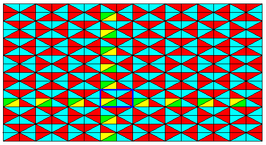
Figure 17c. Alternating color configuration change, originating from the identity element 1 of the initial mesh (Figure 17a), by repeatedly applying to that element the antisymmetry transformations e1tv and e1th .

Figure 17d. Alternating color configuration change, originating from the element m2 of the initial mesh (Figure 17a), by repeatedly applying to that element the antisymmetry transformations e1tv and e1th . The areas as they were highlighted -- yellow -- in the previous Figure are now colored purple (which later will be restored to red). The areas as they were highlighted -- green -- in the previous Figure are restored to blue (their final color).
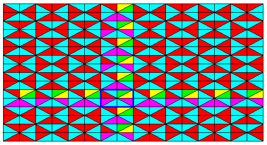
Figure 17e. Alternating color configuration change, originating from the element m1m2 of the initial mesh (Figure 17a), by repeatedly applying to that element the antisymmetry transformations e1tv and e1th . The areas as they were highlighted -- yellow -- in the previous Figure are now colored purple (which later will be restored to red). The areas as they were highlighted -- green -- in the previous Figure are restored to blue (their final color).
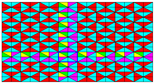
Figure 17f. Alternating color configuration change, originating from the element m1 of the initial mesh (Figure 17a), by repeatedly applying to that element the antisymmetry transformations e1tv and e1th . The areas as they were highlighted -- yellow -- in the previous Figure are now colored purple (which later will be restored to red). The areas as they were highlighted -- green -- in the previous Figure are restored to blue (their final color).
The areas as they were highlighted -- yellow -- in the previous Figure are now colored purple (which later will be restored to red). The areas as they were highlighted -- green -- in the previous Figure are restored to blue (their final color). So we get :

Figure 17g. All elements -- of the antisymmetry pattern to be derived -- of the column and row associated with the initial mesh are now generated.
From Figure 17g it is clear that if we repeatedly subject all the elements of the completed horizontal row of meshes (purple) to the antisymmetry transformation e1tv , i.e. to the transformations . . . tv-2 , e1tv-1 , e1tv , tv2 , e1tv3 , . . . , we get the whole antisymmetry pattern, as given in the next Figure (where purple is finally restored to red).
Figure 18. Resulting antisymmetry pattern derived from the pattern of Figure 7 (and illustrated by the previous Figures) by the above given specifications with respect to the interpretation of the antiidentity transformation e1 . The horizontal as well as the vertical generating translations, th and tv , are replaced by the corresponding antisymmetry transformations e1th and e1tv . And all this results in the pattern of the present Figure.
Let's analyse this antisymmetry pattern.
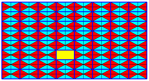
Figure 19. The primitive rectangular point lattice (indicated by strong connection lines) of the initial P2mm pattern. A unit mesh is indicated (yellow).
The next Figure indicates a unit mesh of the antisymmetry pattern of Figure 18. Because a unit mesh should contain all the morphological features (inclusive orientations) of the pattern (of which it is a unit mesh), we have to enlarge the unit mesh as it was in the initial pattern, such that it now -- in the antisymmetry pattern -- comprises four former unit meshes.
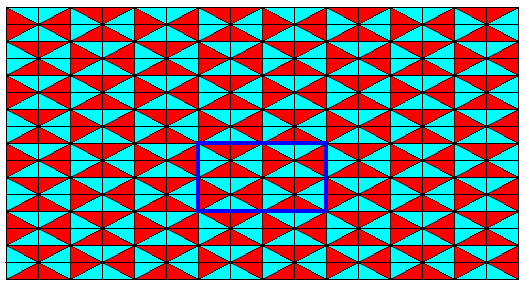
Figure 20. Unit mesh outlined for the antisymmetry pattern of Figure 18. Its area must be four times as big as the unit mesh of the initial pattern in order to include all features of the new pattern.
The next Figure shows that an alleged unit mesh (yellow-outlined) involving four quarters of four original meshes cannot be a unit mesh, because it is not periodically repeated in the pattern (shown by the green-outlined 'mesh').

Figure 20a. The yellow-outlined 'mesh' cannot be a unit mesh, because it does not repeat periodically, as shown by the green-outlined 'mesh'.
The next Figure shows the primitive rectangular point lattice (indicated by connection lines) of the antisymmetry pattern of Figure 18.
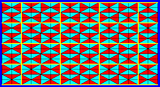
Figure 21. Point lattice, based on the unit mesh indicated in Figure 20, of the antisymmetry pattern of Figure 18 . The lattice connection lines are highligthed by yellow.
The next Figure indicates four non-equivalent generating reflection lines (that can be chosen from an infinity of such lines, because the pattern must be taken to be extended indefinitely over the plane).

Figure 22. Four generating reflection lines of the antisymmetry pattern derived above. They enclose an asymmetric pattern unit.
The next Figure highlights three other asymmetric units generated by the reflections.
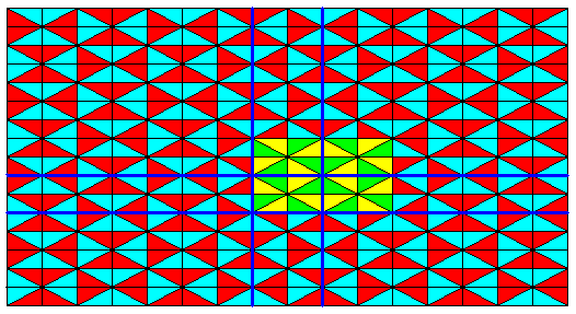
Figure 23. Four asymmetric pattern units of the above derived antisymmetry pattern related to each other by reflection lines. These four units together form a D2 motif.
The D2 motif, as indicated in the previous Figure, builts up the above derived antisymmetry pattern, when translated along two perpendicular directions. Therefore this motif can also be chosen as a unit mesh of the pattern. See next Figure.
Figure 24. The antisymmetry pattern derived above consists of D2 pattern units that are repeated along two perpendicular directions. Therefore the structure of the whole pattern must be P2mm , which in turn means that the transition from the generating symmetry pattern of Figure 7 to the antisymmetry pattern of Figure 18 does not represent a desymmetrization. There is, however, a sense according to which we can speak of a desymmetrization nonetheless, namely when we emphasize the fact that it was necessary to enlarge the unit mesh.
If we take an area representing an original group element (that was a group element of the initial group), and denote it as the identity element 1 , then we can see what other elements are generated by the reflections. See next Figure.
Figure 25. Antisymmetry pattern as derived above. The original area representing the identity element (small rectangle indicated by 1 ) of the generating symmetry group, generates some other elements in virtue of the reflection lines. From the Figure it is clear that in this way only a part of the antisymmetry pattern can be constructed, i.e. some other parts cannot be reached, also not by the inherent genuine translations of the antisymmetry pattern (indicated by yellow arrows). What we construct in this way is a subgroup of the antisymmetry group, and this subgroup has P2mm symmetry.
But, when we also consider the antisymmetry transformations e1tv and e1th , we can generate the whole antisymmetry pattern (which we in fact have done above). The mentioned inherent translations of the antisymmetry pattern are in fact the translations . . . tv-2 , tv2 , tv4 , tv6 , etc., and . . . th-2 , th2 , th4 , th6 , etc., i.e. all the even number of times repeated generating translations of the original group, where e1 is neutralized, because an even number of e1's is equivalent to the identity permutation, which means no color configuration change at all.
The next Figure shows that the in-between areas (as can be seen in Figure 25) of the antisymmetry pattern can indeed be reached by its antisymmetry transformations e1tv and e1th , where e1 is the above defined color configuration swap.
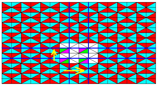
Figure 26. Two (in-between) group elements (of the antisymmetry pattern) generated (from the initial element) by the antisymmetry transformations e1tv and e1th . The yellow arrows indicate the translational component of those antisymmetry transformations. A third (in-between) group element is generated by the transformation e1tve1th = tvth . All these elements are elements of the (above derived) antisymmetry group.
The next Figure shows -- with respect to (analysing) the above derived antisymmetry pattern -- the identity of the (areas representing) group elements generated by the transformations e1tv , tv2 , e1tv3 , tv4 , and e1tv5 . The identity element is chosen as indicated.

Figure 26a. Antisymmetry pattern as derived above.
Group elements generated by the transformations e1tv , tv2 , e1tv3 , tv4 , and e1tv5 .
The next Figure indicates the identities of the in-between elements of the column of elements considered in the previous Figure.
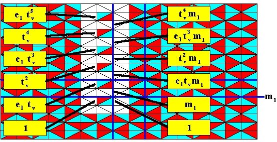
Figure 26b. Antisymmetry pattern as derived above.
The identities of the in-between group elements of the column considered in the previous Figure are indicated. The transformation m1 just means : a reflection in the line m1 .
The next Figure isolates just those in-between elements considered in the previous Figure.
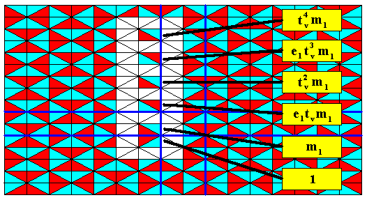
Figure 27. The identities of the above considered in-between group elements of the antisymmetry pattern derived above. The transformation m1 just means : a reflection in the line m1 .
The same goes with respect to the horizontal direction.
The identity element, two reflections, m1 and m2 , and an implied half-turn about the intersection point of the two reflection lines, give rise to the subgroup D2 of the full group represented by the above derived antisymmetry pattern. See next Figure.
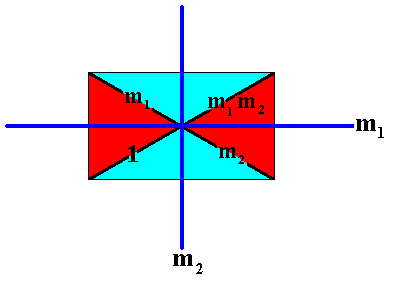
Figure 28. A D2 rosette as a subgroup of the above derived antisymmetry group.
The D2 rosette, depicted in Figure 28, which is a point group, generates a subgroup (which is a plane group) by its being translated as indicated in Figure 25 and, in addition to it, by the (repeated) translation e1tve1th = e1e1tvth = tvth .

Figure 29. Subgroup (green+yellow) of the antisymmetry pattern derived earlier (It is also a subgroup of the generating symmetry pattern [Figure 7 ], because the translations (tv)2 , (th)2 and tvth are also elements of that generating symmetry group).
The next Figure isolates this subgroup.

Figure 30. Isolated subgroup (green+yellow) of the antisymmetry pattern derived earlier.
The next Figure again depicts this subgroup, but now without indication of the generating reflection lines.

Figure 30a. The subgroup (green+yellow) of the antisymmetry pattern derived earlier.
The next Figure indicates the above mentioned translation vectors th2 , tv2 and tvth , generating the subgroup from an initial D2 rosette.
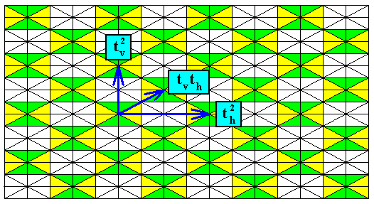
Figure 30b. The three translations (also group elements of the antisymmetry group of Figure 18 ) that generate the subgroup (of the mentioned antisymmetry group).
The next Figure shows that the subgroup is based on a rhombic lattice (which is equivalent to a centered rectangular lattice).

Figure 31. Rhombic point lattice (indicated by red connection lines) underlying the above found subgroup of the antisymmetry group derived earlier.
In Figure 31 we can recognize the equivalent points in the pattern representing the subgroup found above. Each equivalent point (lattice node) is associated with a D2 motif, so the symmetry of the subgroup must be that of C2mm . Therefore the symbol for our derived antisymmetry group must be P2mm / C2mm . The generating symmetry group from which the present antisymmetry group (Figure 18) was derived is depicted in Figure 7.
So if we look to the (antisymmetry) pattern of Figure 18, and first see it as just a symmetry pattern, where the transition from blue to red and vice versa represents just a symmetry transformation, while no antisymmetry transformations are considered to be present (i.e. not interpreting the pattern as representing an antisymmetry group), we find out (Figure 24) that the symmetry is according to the Plane Group P2mm , while we must at the same time admit that the unit mesh of this pattern must be four times as large as the unit mesh of the original pattern. And this can be seen as a desymmetrization.
A black-and-white version of our antisymmetry pattern of Figure 18 is found in Neolithic art (and to this neolithic art pattern all the above considerations were geared) :
Figure 32. Antisymmetry pattern P2mm / C2mm as is present in Neolithic art.
(Adapted from JABLAN, 2002)
This, finally, concludes our investigation of antisymmetry in the plane group P2mm .
In the next document we will look at some subgroups of the plane group P2mm not necessarily associated with antisymmetry or colored symmetry, and then continue our investigation of antisymmetry and subgroups in the remaining plane groups.
e-mail : 
To continue click HERE for further group theoretic preparation to the study of the structure of three-dimensional crystals (crystallography) and the basic symmetry of organisms (promorphology).
Back to 3-dimensional crystals (conclusion), Organic Tectology and Promorphology
Back to subpatterns and subgroups (introduction)
Back to subpatterns and subgroups Part II
Back to subpatterns and subgroups Part III
Back to subpatterns and subgroups Part IV
Back to subpatterns and subgroups Part V
Back to subpatterns and subgroups Part VI
Back to subpatterns and subgroups Part VII
Back to subpatterns and subgroups Part VIII
Back to subpatterns and subgroups Part IX
Back to subpatterns and subgroups Part X
Back to subpatterns and subgroups Part XI
Back to subpatterns and subgroups Part XII
Back to subpatterns and subgroups Part XIII
Back to subpatterns and subgroups Part XIV