(Takes a little while loading the images)
e-mail :

Sequel-15 to the Summary and Evaluation (of the documents XVI -- XXVIII concerning the promorphology of complex-shaped two-dimensional crystals).
This document (Part XXIX Sequel-15) further elaborates on the analogy between crystals and organisms.
Sequel to the Preparations (III) to the Repertoire of the Crystal Analogy
More about the s h a p e s of individual rheocrystals, and crystals in general.
Unfortunately, from what we now have (as was established in the previous document), little can be said about the shape of rheocrystals and its relation to internal structure. Most, or at least many, rheocrystals have a spherical shape (Homaxonia of the Promorphological System). Others will be more or less elongated and adopt cylindrical, biconical or spheroid shapes (Monaxonia), and some will exhibit elongated more or less polyhedric shapes (Stauraxonia).
In earlier documents (Part IV and (especially) Part V, and also Part XXX) we developed -- with respect to sterrocrystals (i.e. solid crystals) -- the concept of the Vector Rosette of Actual Growth which is indicative for the intrinsic shape of the crystal. Earlier we spoke about the directional forces in the crystal, counteracting the overall surface tension which tends to reduce the crystal's shape into a sphere (which in fact is not a definite shape at all). Forces that is to say, which are thus responsible for the resulting definite intrinsic shape of the crystal. HAECKEL, 1917, has called these forces molethynes. We will now -- in order to understand the intrinsic shape of sterrocrystals as well as that of rheocrystals -- investigate the relationship between the Vector Rosette of Actual Growth (in fact the Reduced Vector Rosette of Actual Growth) of a given crystal and its molethynes.
The (reduced) Vector Rosette of Actual Growth is a figure that one obtains as follows : From the geometric center of a fully grown crystal, grown in uniform conditions, we draw lines to all the crystal's corners. See next Figure.
Figure above : A two-dimensional sterrocrystal (or a projection of a three-dimensional crystal onto the plane of the drawing along one of its axes).
The (red) lines, ca, cd, cf, ch, cj, together form the Vector Rosette of Actual Growth. Each such line indicates the direction of a local growth maximum, and its length indicates the relative growth rate in that direction, all reckoned from a point (c) which is considered to be the starting point of the development of the crystal. Because the growth of a fast growing face can be terminated early on in development (when slowly growing adjacent and tapering faces are present), the length of the lines do not actually give the relative growth rates, but only the effective growth rates, by indicating the actual extent of the growth in terms of the distance actually traversed, i.e. the distance between the center of the crystal and the (peripheral) point actually reached by the crystal in that direction ( When this distance is divided by the time that was available for the crystal to grow, we get a growth rate anyway, which is then an effective growth rate). It is because of these distances from the center, actually accomplished in the given directions, while only such distances are considered that represent local maxima, that we call the set of red lines (i.e. the set of lines going from the center of the (fully grown) crystal to its corners) the (reduced) Vector Rosette of Actual Growth (where "reduced" means that only the growth directions from the center to the corners are taken into account).
When we look to the actually accomplished growth in all directions (fanning out from the center), we see local maxima and minima along the way : If we begin at a and let the line, determined by ca, rotate about the center (c) of the crystal and inspect the actually accomplished growth, reckoned from the center (to the boundary points of the crystal), then we see, to begin with, a local maximum at a , then a local minimum at b , then a local maximum at d , then a local minimum at e , then a local maximum at f , then a local minimum at g , then a local maximum at h , then a local minimum at i , then a local maximum at j , and then, finally, a local minimum at k .
The lines cb, ce, cg, ci, ck are the growth directions of the crystal's extant faces.
It is clear that the growth directions from the center of the crystal to the local maxima represent local maximal forces that counteract the tendency of the overall surface tension to contract the crystal into a sphere (or a circle in the two-dimensional case, or projection). While the locally maximal forces of expansion of a growing crystal, whether or not these forces had the chance to express themselves in the shape features of the crystal, are in fact the crystal's molethynes (the directional forces), the set of such forces, (but now) insofar as they are actually expressed in the shape of the (fully grown) crystal, is (defined as) the Rosette of Effective Molethynes of the crystal. And it is clear that this set is wholly equivalent with the Vector Rosette of Actual Growth (as this concept was developed in Part IV and Part V).
Although the theory of the development of crystal faces is already discussed in Part IV and Part V , we will here repeat a few things and add others. For the explanations a two-dimensional ionic sterrocrystal is used. It consists of two types of ions, one positive and one negative. While the crystal forms, these ions arrange according to a hexagonal net (See Figure below ), consisting of the periodic stacking of rhombic (angles, 600 and 1200) building blocks, each containing one ion of one type and one ion of the other. See next Figures.
Figure above : Internal structure of a two-dimensional ionic crystal (consisting of two different sorts of ions of opposite electrical charge).
The total symmetry of this structure is according to the Plane Group P3m1. Its Point Group ( = Crystal Class) is 3m (isomorphic to D3). To study this Plane Group geometrically, click HERE for the document where it is discussed (First Part of Website, Internal Structure of Crystals, Part V).
Several different atomic aspects presented by the crystal to the nutrient environment are shown in the next Figure. Such an aspect represents a possible crystal face.
Figure above : Some atomic aspects that can be found in the structure depicted in the Figure above (and below). They are the aspects of possible crystal faces.
The next Figure shows the hexagonal net (lattice) according to which the (chemical) motifs are arranged.
Figure above : Hexagonal lattice, underlying the structure of the (trigonal) structure depicted above . The motifs, placed in this lattice, and their orientation, determine the total symmetry of the pattern to be that of the Plane Group P3m1. The symmetry of the motif is trigonal. The meshes of the hexagonal net are rhombs with angles of 600 and 1200. Each mesh contains two ions. The Figure represents a two-dimensional ionic sterrocrystal bounded by six A-faces (For these, see Figure above ).
Figure above : A row of (rhombic) building blocks is highlighted (green) in order to show a potential face within the crystal (In the next Figures highlighted building blocks are colored dark blue).
Figure above : A row of (rhombic) building blocks is highlighted (dark blue) in order to show a potential face within the crystal.
Figure above : Indication and outline of a possible crystal face in the ionic sterrocrystal of the above Figures. The direction of the face is determined by going along the building blocks as follows : two steps along one direction, one step along the other, then again, two steps along the one direction, one step along the other, etc.
Because the apical areas of the building blocks are empty, the line (green), that is supposed to indicate the possible crystal face (type A), is now drawn such that it touches the relevant ions :
Figure above : Correct indication (green line) of a possible crystal face in the ionic sterrocrystal of the above Figures. The indicated possible face turns out to be of type A (See Figure above ). See also next Figure.
Figure above : Correct indication (green line) of a possible type-A crystal face in the ionic sterrocrystal of the above Figures. For comparison : Indication of a type-A face bordering the hexagon-shaped crystal.
The next Figure explores another possible face (direction).
Figure above : A row of (rhombic) building blocks is highlighted (dark blue) in order to show another potential face within the ionic sterrocrystal of the above Figures. The course is now : three steps in one direction, one step in the other. See also next Figure.
Figure above : Correct indication (lower green line) of a possible crystal face (as already indicated in the previous Figure), together with an indication of a B-fase (upper green line), in the ionic sterrocrystal of the above Figures. The indicated possible new face ( B' ) turns out to be of a type not yet discussed. It is similar to type B (See Figure above ), but differs by its broader spacing (i.e. the atomic aspect of both faces consist of 'grey' ions, but the spacing of these ions along the face is larger in the new face).
Now that we know how potential crystal faces are geometrically determined by the internal (geometric) structure of a crystal, we can relate these faces, and their directions of growth to the above discussed Rosette of Effective Molethynes (or, equivalently, the Vector Rosette of Actual Growth). See next Figures.
Figure above : It is shown how a two-dimensional sterrocrystal, having a certain shape, can be built by the stacking of (in this case) rectangular building blocks (In fact, only the rectangular net is shown, without its material content, i.e. without motifs).
Figure above : The faces of the crystal in the above Figure are explicitly outlined. Their direction of growth is perpendicular to them (i.e. perpendicular to their outlines).
Figure above : Vector Rosette of Actual Growth, consisting of the vectors 1, 2, 3, 4 and 5. The vectors originate from a point within the crystal that is considered to represent the starting point of the development of the crystal. Perpendicular to these vectors are possible crystal faces, here explicitly shown for the vector 3. The Vector Rosette of Actual Growth expresses the pattern of direction and magnitude of growth maxima, and is equivalent to the Rosette of Effective Molethynes (effective directional forces of the substance under given conditions).
Figure above : Crystal faces, represented by the vectors 1, 2, and 5 depicted in the previous Figure.
The next Figure depicts a rectangular two-dimensional sterrocrystal, also based on a rectangular net (lattice).
Figure above : Rectangular crystal and its Rosette of Effective Molethynes (red lines) originating from the center of the crystal. Each molethyne represents a growth direction of a possible face. The latter is perpendicular to its growth direction. For the upper left molethyne this is shown.
So, for a growing crystal, we can say that there is an overall surface tension that tends to contract the crystal into a sphere, while its effective molethynes, if they are strong enough (which is always the case in sterrocrystals), counteract this tendency, resulting in a definite shape of the crystal.
Dendritic Crystals, fast Molethynes.
We stated above that some of the fast molethynes in a given sterrocrystal cannot express themselves because they are cut off early on in the crystal's development (in virtue of slow growing tapering adjacent faces). But when, from the outset, we have to do with a very fast growing sterrocrystal, no faces will have the chance to develop, and the fast molethynes express themselves as branches going out from the center of the crystal. We know such crystals already in the form of star-shaped snow crystals. Here again are two examples.
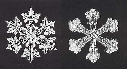
But branched crystals can also be formed by other substances. The next two Figures depict branched salt crystals (NaCl).
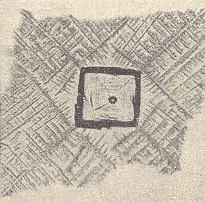
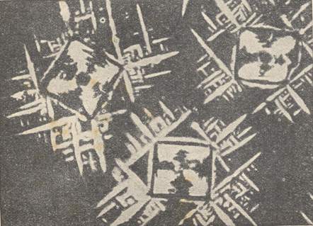
Figure above : A two-dimensional square crystal (blue). Its internal structure is based on a square net. The four faces (implying two directions) of the square crystal are the slowest growing faces, and therefore ultimately survive (See Figure 7 in Part IV ).
Figure above : Growth directions (arrows) of the four faces of the square crystal of the previous Figure. They are the directions of slowest growth. We consider two such directions to be present, expressing the fact that each consists of two equivalent opposites.
Figure above : Fast growing faces (red), implying two growth directions (perpendicular to the faces), a and b (arrows). During growth of the crystal these faces have disappeared. The two fast growth directions correspond to the crystal's effective molethynes (each consisting of two equivalent opposites). See next Figure.
Figure above : The four (2+2) effective molethynes, radiating from the crystal's center to its corners. The directions in which these molethynes point, are the directions a and b of the previous Figure, i.e. the directions of the effective molethynes correspond to the directions of fast growth.
Figure above : As a result of fast growth of the initial (slowly grown) two-dimensional square crystal (blue), branches appear (dark blue, of them only their directions are indicated). The directions of these branches correspond to the directions of fast growth (a and b), and thus correspond to the crystal's molethynes.
Ice crystals
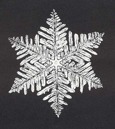
Figure above : Branched snow crystal.
(Presumably) very small hexagonal central plate adorned with six similar branched extensions at its corners. The secondary branches stand off from the main branch (of which, as has been said, there are six) at angles of 600.
(After BENTLEY and HUMPHREYS, Snow Crystals, 1931, 1962.)
The next Figures show that the first-order branches in star-shaped snow crystals originate from the corners of the initial hexagonal plate if there is any.
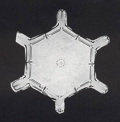
Figure above : Hexagon-shaped snow crystal with incipient branches at its corners.
(After BENTLEY and HUMPHREYS, Snow Crystals, 1931, 1962.)
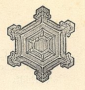
Figure above : (More or less distorted) hexagon-shaped snow crystal with incipient branches at its corners.
(After HAECKEL, Kristallseelen, 1917.)
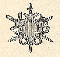
Figure above : Hexagon-shaped snow crystal with branches at its corners.
(After HAECKEL, Kristallseelen, 1917.)
In a later series of Figures we will interpret these branches, including secondary, tertiary, etc. branches, in terms of molethynes of the snow crystal ( These molethynes are present, whether or not the snow crystal has branches : It is the branches by which we can detect the molethynes). But before we do so, we repeat something about the crystalline structure of Ice, as it was investigated in Part XXIX Sequel-7 .
Figure above : Structure of ice, seen along the crystallographic c-axis.
Each dot (red or blue) represents a water molecule. Each such water molecule connects with four others by hydrogen bonds. Three such bonds shown for each water molecule. The fourth bond is perpendicular to the plane of the drawing. The blue and red dots (both representing water molecules) do not lie in the same plane (when the structure is seen three-dimensionally). The blue dots lie in one plane, the red dots in another. And, of course, when seen as a projection along the crystallographic c-axis (which is perpendicular to the plane of the drawing), i.e. a projection onto the plane of the drawing, the blue and red dots lie in the same plane.
Figure above : Same as previous Figure.
Possible rhombic unit cell indicated (light blue). The the center of each hexagon is the location of a 63 screw axis (four of them indicated), if the Figure is interpreted as representing a 3-dimensional view (down the c-axis).
If the Figure is 2-dimensionally interpreted, then we see a rhombic unit mesh, containing two 3-fold rotation axes (coinciding with the two molecules of that mesh), and a 6-fold rotation axis at each of its corners.
Figure above : In the previous Figure we could see that the Ice structure is according to a hexagonal net (i.e. a hexagonal two-dimensional lattice) if it is projected along the c-axis. This net consists of a tiling of the plane by two types (with respect to orientation) of equilateral triangles. Two such triangles, one of each type, form a rhomb (with 600 and 1200 angles). These rhombs are periodically repeated. Six triangles make up a hexagon. And also such a hexagon is periodically repeated. This is explicitly indicated in the next Figure.
Figure above : Same as previous Figure.
The Ice structure is according to a hexagonal net (i.e. a hexagonal two-dimensional lattice) if it is projected along the c-axis. This net consists of a tiling of the plane by two types (with respect to orientation) of equilateral triangles. Two such triangles, one of each type, form a rhomb. These rhombs are periodically repeated. Six triangles make up a hexagon. And also such a hexagon is periodically repeated (See next Figure).
Figure above : Same as previous Figure.
The hexagons (each consisting of six equilateral triangles) are periodically repeated throughout the ice structure.
Now we will discuss the branches of snow crystals and their relations to the molethynes of ice crystals in general.
Figure above : Hexagonal net (lattice), according to which the water molecules (which themselves and their bondings are not shown) of a snow crystal are arranged in a periodic array, seen in a projection along the crystallographic c-axis (which is perpendicular to the plane of the crystal's hexagonal outline). The net consists of a periodic stacking of rhombs (figures with four equal sides forming non-900 angles, in the present case angles of 600 and 1200). These rhombs are each divided into two equilateral triangles. The three previous Figures depicted this same net, but there this net was provided with content : water molecules and the bonds connecting them.
Figure above : (As we know already) the net can be interpreted as a periodic stacking, either of rhombs or of hexagons. It is not a periodic stacking of triangles, but only a plane-filling tiling of such triangles ( This is because the triangles do not all have the same orientation).
Figure above : Projection along the c-axis of a snow crystal (blue), that has the shape of a (very thin) hexagonal plate. The six faces bounding the hexagonal crystal are the slowest growing faces (See also next Figure). Faster growing possible faces have disappeared during the development of the crystal.
Figure above : The directions of growth of the actual existing (slowest growing) faces of the crystal are indicated by arrows.
Figure above : Fast growing possible faces of the crystal (depicted in the previous two Figures) are indicated (red) together with their directions of growth (arrows), a, b, c (including their opposites). These directions will be materialized by branchings, when further growth of the crystal is (very) fast. These branches, and also their side-branches (standing off at 600) represent the effective molethynes of the snow crystal. As such the molethynes obviously determine the shape of a fast growing snow crystal. But they also determine the shape of the crystal (as seen in the mentioned projection) in the case of slow growth, i.e. they are also responsible for the hexagonal shape of plate-like snow crystals. In this case (of slow growth) the fast growing faces diminish gradually until they have vanished altogether and thus have been transformed into corners.
The next three Figures depict a smaller hexagonal snow crystal as initial (slow) growth stage. Such a crystal, as also the larger one above, is supposed to have been generated by slow growth, i.e. by slow crystallization. But, from this stage on it is supposed that the crystallization proceeds very fast, resulting in branches to appear. First the primary six branches at the six corners of the initial hexagon-shaped crystal appear, then from these the secondary branches (going off at 600), then from these in turn the tertiary branches (also going off at 600, in this case from the secondary branch), etc.
Figure above : Small initial hexagon-shaped snow crystal (seen as a projection along the c-axis onto the plane of the hexagonal plate of the crystal). The generation of this crystal, that came into being by slow crystallization, is followed by fast growth, resulting in branches. The six primary branches (which here are depicted only as directions) representing growth directions of fast growing faces are indicated as dark blue lines going off from the six corners of the initial hexagonal plate. (See also previous Figure). The fast growing faces themselves do not develop (as faces). The three directions (including their opposites) are labelled a, b, c.
The next two Figures depict the secondary and tertiary branches (as with the primary branches, only their direction -- not their structure -- is drawn).
Figure above : Same as previous Figure. Secondary branches added, together with the indication (i.e. labels) of their directions. Also they, only show the directions a, b and c, i.e. other directions do not occur among them.
Figure above : Same as previous two Figures. Tertiary branches added (red lines, red labels). Also they, show only the directions a, b and c, other directions do not occur among them. Again, the drawing only concentrates on the directions of the branches, not on their (relative) lengths, nor on their (internal) structure.
All these branches (primary, secondary, tertiary, etc.) represent, with their directions, the set of effective molethynes of the snow crystal, and of ice crystals in general.
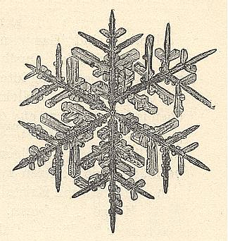
Figure above : Star-shaped snow crystal. Its branches originate from a very small seed.
(After HAECKEL, Kristallseelen, 1917.)
This concludes the main part of our discussion of molethynes in crystals. In the next document we discuss shape changes in snow crystals as a result of metamorphism.
e-mail :
To continue click HERE for further study of the Theory of Layers, Part XXIX Sequel-16.