
e-mail :

Sequel to Group Theory
As always, we start with reminding the reader about the "Important Remark" near the end of Part III of Group Theory (To see it, click HERE and then go to (end of) Part III ), a Remark concerning the direction of reading products of group elements, like, say, apq. We read such products (from that Remark onwards) from back to front. Thus (with respect to apq) first q, then p, and then a.
Infinite two-dimensional periodic patterns, or Ornaments (sequel)
In the previous document we investigated antisymmetry, subpatterns and subgroups of the plane group C2mm. Here we will continue this investigation.
The next antisymmetry pattern to be derived from the generating C2mm pattern as depicted in Figure 5 of the previous document can be obtained by replacing the generating NE translation tne by its corresponding antisymmetry translation e1tne and at the same time replacing the generating horizontal reflection mh by its corresponding antisymmetry relection e1mh , and where the antiidentity transformation e1 is again interpreted as the color permutation (Blue Red) (cycle notation) with respect to the background color, which initially is set to blue. We will derive the antisymmetry pattern in several steps, where every time first the colors green and purple will be used, which later will be replaced by blue and red.
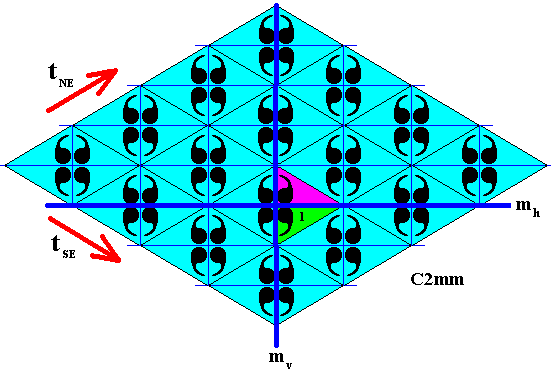
Figure 1. First stage in the derivation of the antisymmetry pattern as defined above. The (area representing the) identity element ( 1 ) is subjected to the antisymmetry reflection e1mh effecting a color change.
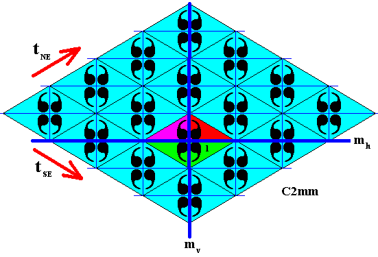
Figure 2. Second stage in the derivation of the antisymmetry pattern as defined above. Subjection of the two elements already present, to the generating vertical reflection mv (which is not an antisymmetry transformation) does not effect a color change. Three elements are now generated, and, together with the presupposed identity element, we have now four elements.
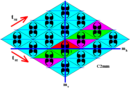
Figure 3. Third stage in the derivation of the antisymmetry pattern as defined above. Subjection of the four elements already present, to the antisymmetry translation e1tne results in alternating color change.

Figure 4. Fourth stage in the derivation of the antisymmetry pattern as defined above. Subjection of the elements already present, to the generating SE translation tse (which is not an antisymmetry transformation) does not effect color changes.
Restoring green to blue and purple to red, gives the following antisymmetry pattern :
Figure 5. Final stage in the derivation of the antisymmetry pattern as defined above. The colors are restored. As always, the pattern must be imagined to extend indefinitely over the plane.
The point lattice of the just derived antisymmetry pattern is indicated in the next Figure.

Figure 6. Point lattice (indicated by strong dark blue connection lines) of the just derived antisymmetry pattern. It is an oblique lattice. Compare with the point lattice of the generating C2mm pattern depicted in Figure 2 of the previous document.

Figure 7. Point lattice (indicated by strong dark blue connection lines) of the just derived antisymmetry pattern. A unit mesh is indicated by alternative colors.
If we isolate the set of blue elements of the just derived antisymmetry pattern we get the following :
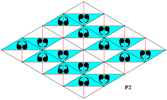
Figure 8. Subpattern (blue elements) of the antisymmetry pattern derived above (Figure 5 ).
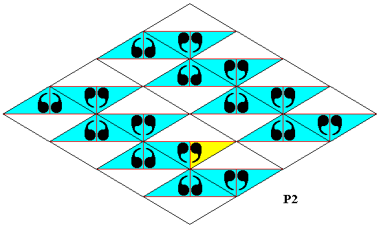
Figure 9. Subpattern (blue elements) of the antisymmetry pattern derived above (Figure 5 ). Some superfluous lines removed. The original (area representing the) identity element (as it is present in the generating C2mm pattern as well as in the above derived antisymmetry pattern) is indicated (yellow).
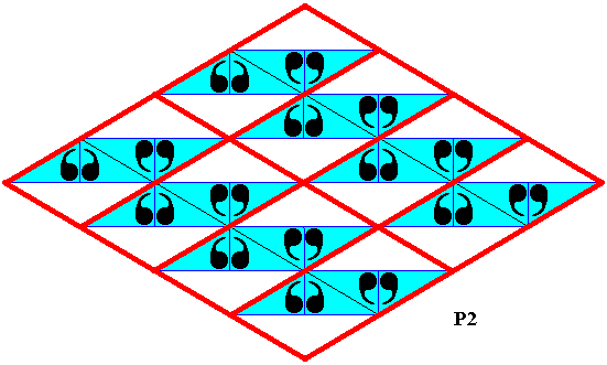
Figure 10. Point lattice (indicated by strong red connection lines) of the subpattern (blue elements) of the antisymmetry pattern derived above (Figure 5 ). It is an oblique lattice.
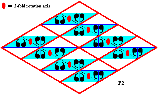
Figure 11. The subpattern turns out to consist of motifs each having C2 symmetry, i.e. each motif possesses a 2-fold rotation axis, indicated in the Figure by a small solid red ellipse ( The pattern possesses much more of such axes). Such a 2-fold motif (consisting of four commas) is repeated by two independent translations (See next Figure).
The next Figure indicates the two generating translations of the subpattern of blue elements.
Figure 12. The subpattern consists of motifs each having C2 symmetry, which are repeated by the two translations indicated. This demonstrates that the symmetry of the subpattern is that of the plane group P2 . The original (area representing the) identity element of the generating C2mm symmetry pattern and also of the antisymmetry pattern derived from it, is indicated (yellow).
The next Figure shows how the (areas representing) group elements should be conceived.

Figure 13. Areas representing group elements (green or yellow) of the subpattern derived above.

Figure 14. Areas representing group elements (green or yellow) of the subpattern derived above. We can choose any such area to represent the identity element of the subpattern. A choice is indicated (blue). The area that can (just) r e p r e s e n t the identity element can be the triangle containing two commas, while the area that in fact is the identity element is indicated by the blue region (still containing two commas). If we compare this with with Figure 12 we see that this identity element (involving two commas) is different from the original identity element (involving one comma), which implies that the P2 subpattern (of the antisymmetry pattern) is not a s u b g r o u p of the generating C2mm pattern, nor of the antisymmetry pattern derived from it. Therefore the symbol for the antisymmetry group representing this antisymmetry pattern (Figure 5 ) must read C2mm / *P2 .
The next antisymmetry pattern to be derived from the generating C2mm pattern as depicted in Figure 5 of the previous document can be obtained by replacing the generating NE translation tne by its corresponding antisymmetry translation e1tne and at the same time replacing the generating vertical reflection mv by its corresponding antisymmetry reflection e1mv , and where the antiidentity transformation e1 is again interpreted as the color permutation (Blue Red) (cycle notation) with respect to the background color, which initially is set to blue. We will derive the antisymmetry pattern in several steps, where every time first the colors green and purple will be used, which later will be replaced by blue and red.
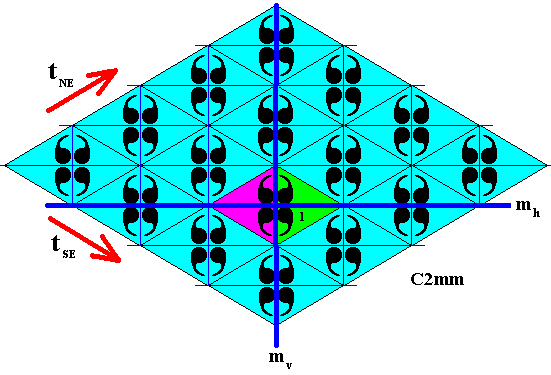
Figure 15. First phase of the derivation of the antisymmetry pattern as defined above. The identity element is first subjected to the vertical antisymmetry reflection e1mv which entails a color change. Subsequent reflection of both elements in the horizontal reflection line mh does not involve color change. We have now obtained four elements of the antisymmetry pattern.
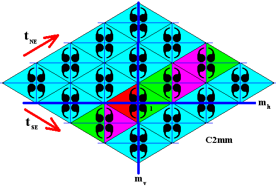
Figure 16. Second phase of the derivation of the antisymmetry pattern as defined above. When the four elements already present are subjected to the antisymmetry translation e1tne , which is an antisymmetry transformation, an alternation of colors appears, because e1tnee1tne = (tne)2 (no color change involved), e1tnee1tnee1tne =
(e1tne)3 = e1(tne)3 (color change involved), etc.

Figure 17. Third phase of the derivation of the antisymmetry pattern as defined above. When we repeatedly apply the SE translation tse (which is not an antisymmetry transformation), no color change is involved.
If we now restore green to blue and purple to red we get the following antisymmetry pattern :
Figure 18. Final phase of the derivation of the antisymmetry pattern as defined above. The colors are restored : green ==> blue, and purple ==> red.
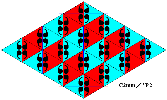
Figure 19. Same as previous Figure, but with the indications of mirror lines removed.
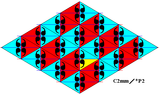
Figure 20. Same as previous Figure. The original (area representing the) identity element of the generating C2mm symmetry pattern (Figure 5 of the previous document ) as well as of the antisymmetry pattern (Figure 18 ), is indicated (yellow).
The next Figures indicate a possible point lattice of the just derived antisymmetry pattern.

Figure 21. Point lattice (indicated by strong dark blue connection lines) of the antisymmetry pattern of Figure 18 , derived from the generating C2mm pattern of Figure 5 of the previous document by replacing the NE generating translation and the generating vertical reflection by their corresponding antisymmetry transformations. With respect to geometry it is a rhombic lattice, but crystallographically it is an oblique lattice (that happens to be rhombic as one of its species), because the motif making up the content of a unit mesh has a half-turn but no mirror lines.
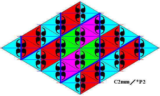
Figure 22. Point lattice (indicated by strong dark blue connection lines) of the antisymmetry pattern of the previous Figures. A unit mesh is indicated by alternative colors.
The point lattice of the C2mm / *P2 antisymmetry pattern, as depicted in the two previous Figures, is, however, not the most preferable possibility. A lattice with a smaller unit mesh is possible, as the next Figures show.
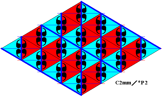
Figure 22a. Alternative and preferable point lattice (indicated by strong dark blue connection lines) of the antisymmetry pattern of the previous Figures. The lattice meshes are smaller than those in the previous Figures. It clearly is an oblique lattice.
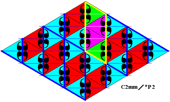
Figure 22b. Alternative and preferable point lattice (indicated by strong dark blue connection lines) of the antisymmetry pattern of the previous Figures. A unit mesh is indicated by yellow outline and alternative colors.
In the next two Figures the antisymmetry pattern is extended in order to clearly show the repetition of the (smaller) unit mesh.
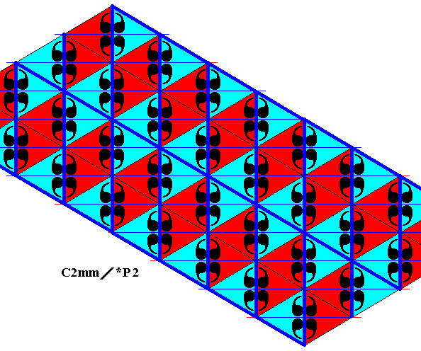
Figure 22c. Same as previous two Figures (Alternative point lattice with smaller meshes). Pattern extended.

Figure 22d. Same as previous Figure (Alternative point lattice with smaller meshes). Pattern extended. Periodic repetition of unit mesh (parallelogram) indicated by colors.
Still another point lattice (next Figure) is possible for our antisymmetry pattern, but this one is fully equivalent to the one described in the above Figures (22a, 22b, 22c, 22d). In both cases the unit mesh contains eight motif units (commas).
Figure 22e. Point lattice (indicated by strong blue connection lines) equivalent to that depicted in the above Figures. The unit mesh of both lattices contains eight motif units (commas), while the lattice depicted in Figure 22 contains sixteen motif units (commas).
In order to determine the identity of the above derived antisymmetry pattern, as depicted in Figure 18 , let us isolate the set of blue elements from it :
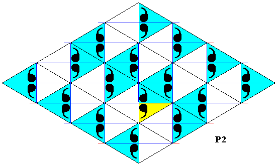
Figure 23. Isolation of the subpattern (blue elements) of the above derived antisymmetry pattern. The area originally representing the identity element of the generating C2mm pattern as well as of the antisymmetry pattern derived from it, is indicated (yellow).

Figure 24. Inspecting the subpattern, we can see that a 2-fold motif (i.e. a motif -- consisting of four commas -- of which its halves are related to each other by a half-turn) is repeated by two independent translations (indicated by arrows, which are their vectors). So the symmetry of the subpattern is according to the plane group P2 .

Figure 25. Point lattice (indicated by strong red connection lines) of the isolated subpattern. It is an oblique lattice. Compare with the lattice of the antisymmetry pattern as depicted in Figure 22e .
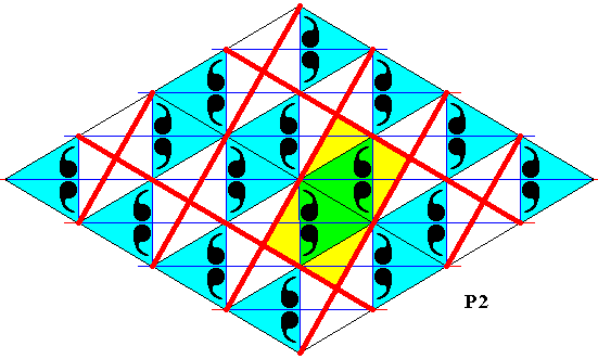
Figure 26. Point lattice (indicated by strong red connection lines) of the isolated subpattern. A unit mesh is indicated by alternative colors.
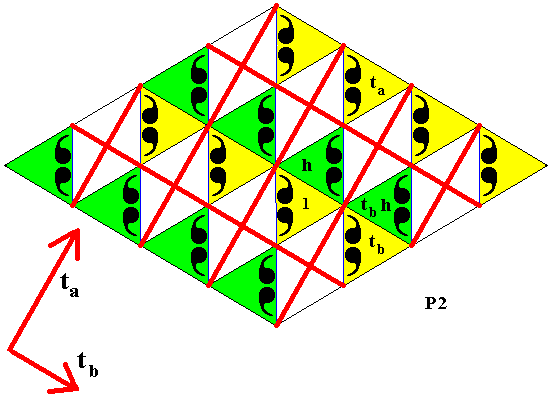
Figure 27. Areas (green or yellow) representing group elements of the above derived subpattern. The generating half-turn is indicated as h , and the generating translations by ta and tb ( Their vectors are given at the bottom-left corner of the Figure). We can clearly see that the area representing the identity element of the subpattern includes two commas, while that of the identity element of the generating C2mm symmetry pattern and of the antisymmetry pattern derived from it, includes only one comma. So the subpattern, although a group, namely a P1 group, is not a s u b g r o u p of the generating pattern nor of the antisymmetry pattern. This means that the symbol for the antisymmetry group representing the antisymmetry pattern derived above (Figure 18 ) must read C2mm / *P2 .
Subgroups
We will now give some patterns representing some subgroups of the plane group C2mm, subgroups not necessarily connected with antisymmetry desymmetrizations.
Recall that a subgroup S of a group G is a group of which all elements are also elements of group G, and, especially, that the identity element is common to both, and that there are elements (at least one) of G that are not in S.
The pattern representing the full (plane) group C2mm and also the subgroup patterns representing line groups or plane groups, must be imagined to extend indefinitely over the plane (A line group pattern in only one direction [and its opposite], a plane group pattern in two directions [and their respective opposites] ). Such groups are of infinite order, i.e. they contain an infinite number of group elements. This in contradistinction to point groups (i.e. symmetry groups, where in the patterns representing them, at least one point is invariant under all symmetry transformations of the given group). Such a point group, if it is discrete (i.e. not containing rotations involving infinitesimal angles), has a finite number of group elements. Examples are the dihedral groups D1 (two elements) and D2 (four elements) and the cyclic group C2 (two elements), which we will encounter below as finite subgroups of the plane group C2mm, which itself is infinite.

Figure 28. If we apply the horizontal generating reflection to the identity element, we get a new element. If we subject the latter in turn to the generating horizontal reflection we are back at the identity element again : mhmh = 1 . In this way we obtain the subgroup D1 (yellow)(dihedral group of order 2).

Figure 29. If we apply the vertical generating reflection to the identity element, we get a new element. If we subject the latter in turn to the generating vertical reflection we are back at the identity element again : mvmv = 1 . In this way we obtain the subgroup D1 (yellow) (dihedral group of order 2).

Figure 30. If we apply the half-turn h (lying at the intersection point of the two generating mirror lines) to the identity element, we get a new element. If we subject the latter in turn to that half-turn we are back at the identity element again : hh = 1 . In this way we obtain the subgroup C2 (yellow) (cyclic group of order 2).
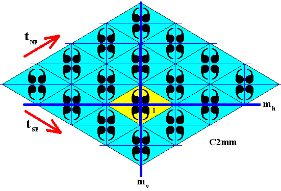
Figure 31. If we apply both generating reflections to the identity element, we get a pattern of four elements. It is the subgroup D2 (yellow) (dihedral group of order 4).
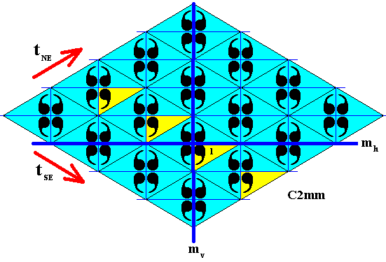
Figure 32. When we subject the identity element repeatedly to the SE translation we get -- as a subgroup -- a frieze pattern (yellow) with a symmetry according to the line group p11 .

Figure 33. When we subject the identity element repeatedly to the generating NE translation we get -- as a subgroup -- a frieze pattern (yellow) with a symmetry according to the line group p11 .
The next subgroup of the plane group C2mm can be generated by the vertical generating reflection (i.e. reflection in the line mv ) and the SE translation. It will turn out to have the structure of the plane group Cm . We will generate this subgroup in several steps.
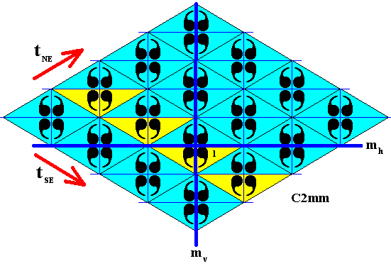
Figure 34. First stage in the generation of the subgroup Cm as defined above.
When we subject the identity element to the vertical generating reflection we get a second element. When we now subject both these elements (1 and mv) repeatedly to the SE translation, we get a strip-like pattern as indicated (yellow).
Because one of the generators of our subgroup is the vertical reflection in the line mv , it can and must be combined with already generated group elements. This means that we reflect the latter in the line mv . See next Figure.

Figure 35. Second stage in the generation of the subgroup Cm .
Implication of new elements by the reflection in the line mv (which is an element of the subgroup).
Because the SE translation is an element of the subgroup it must be combined with the elements already generated, resulting, finally, in our subgroup. See next Figure.
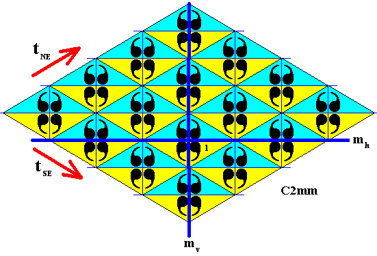
Figure 36. Final stage in the generation of the subgroup Cm (yellow).
The SE translation, which is an element of the subgroup, is repeatedly applied to all elements already generated. This results in the subgroup Cm . As we can see in Figure 9 of the previous document this subgroup is involved in the antisymmetry group C2mm / Cm . For the analysis of this subgroup see Figure 11 of the previous document.
Yet another subgroup of the plane group C2mm can be generated by the horizontal generating reflection, i.e. reflection in the line mh , and the SE translation. The structure of this subgroup turns out to be that of the plane group Cm . We will generate this subgroup in several steps.
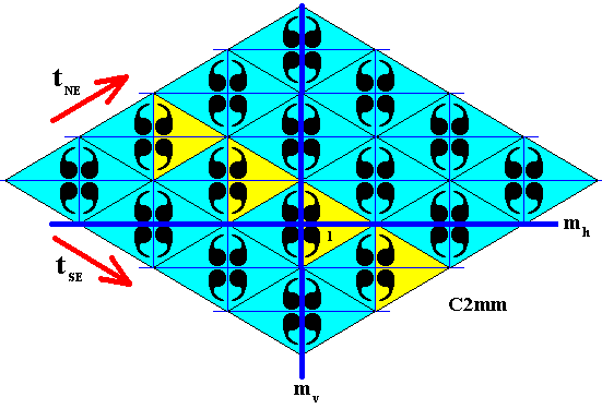
Figure 37. First stage of the generation of the subgroup Cm as defined above.
When we apply the horizontal generating reflection to the identity element we get a second element. We have now two elements of the subgroup to be generated. When we now apply to these elements the SE translation repeatedly, we get a strip-like pattern as indicated (yellow).

Figure 38. Second stage of the generation of the subgroup Cm as defined above.
Reflection in the line mh (which is an element of the subgroup) of the elements already generated creates more elements of the subgroup (yellow).
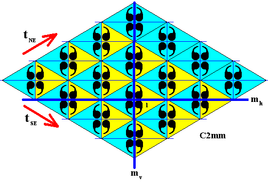
Figure 39. Third stage of the generation of the subgroup Cm as defined above.
Repeated application of the SE translation to the elements already generated, creates still more elements of the subgroup (yellow).

Figure 40. Fourth stage of the generation of the subgroup Cm as defined above.
Generation of new elements (at the bottom right) by the application of the SE translation (Recall that the pattern of the full group -- C2mm -- must be imagined to be extended indefinitely over the plane with its blue elements).
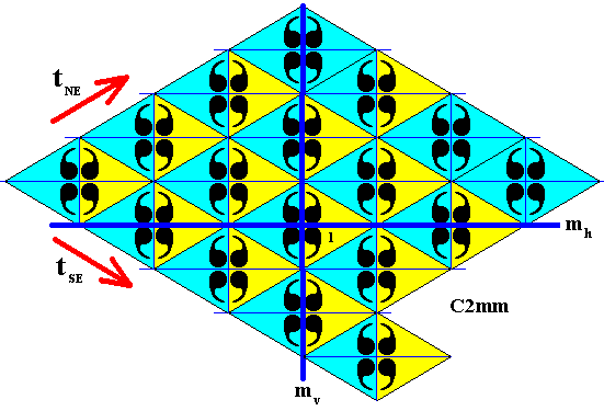
Figure 41. Fifth stage of the generation of the subgroup Cm as defined above.
Reflection of the new elements, generated in the previous Figure, in the line mh (which reflection is an element of the subgroup) creates still more elements (yellow, at the top right) of the subgroup.
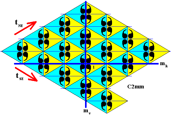
Figure 42. Final stage of the generation of the subgroup Cm as defined above.
Repeated application of the SE translation to the newly (previous Figure) generated elements creates still more elements (yellow) of the subgroup.
Let us analyse this last subgroup (Figure 42) as to its symmetry.
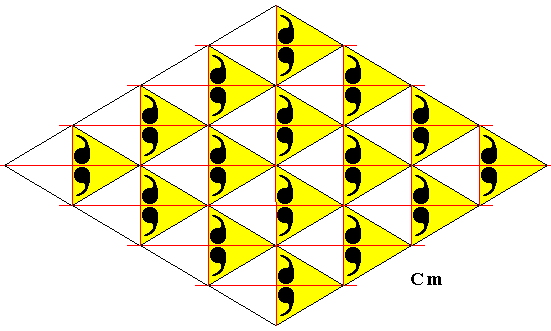
Figure 43. The pattern representing the subgroup of the full group C2mm , as indicated in Figure 42, is isolated (As always, the pattern must be imagined to be extended indefinitely over the plane).
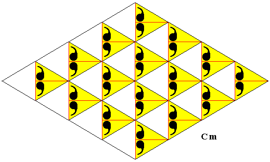
Figure 44. The pattern representing the subgroup of the full group C2mm , as in the previous Figure, but now with some auxiliary lines removed in order to let the motifs s.str. come out more clearly.
The next Figures indicate the point lattice of the subgroup of the previous Figure.

Figure 45. Point lattice (indicated by strong dark blue connection lines) of the pattern representing the subgroup as given in the previous Figure. It is a rhombic lattice. Compare with the (rhombic) lattice of the full group (C2mm) in Figure 2 of Part XXIII.
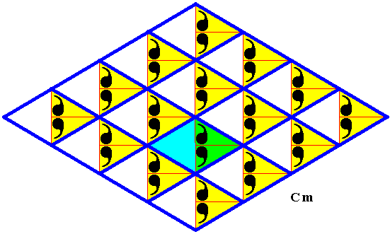
Figure 46. Point lattice (indicated by strong dark blue connection lines) of the pattern representing the subgroup as given in Figure 44. A unit mesh is indicated by alternative colors.

Figure 47. Point lattice (indicated by strong dark blue connection lines) of the pattern representing the subgroup as given in Figure 44. The two generating translations are indicated (purple arrows).
As one can see in Figure 47, the subgroup consists of mirror symmetric motifs repeated by two independent non-perpendicular translations. And because the mirror symmetry of each motif is also a symmetry transformation of the whole pattern (representing the subgroup under investigation), the structure of our subgroup must be that of the plane group Cm (If the lattice were primitive rectangular the symmetry of the pattern would be according to the plane group Pm). One can equivalently underly the structure of the pattern representing our subgroup with a centered rectangular lattice.
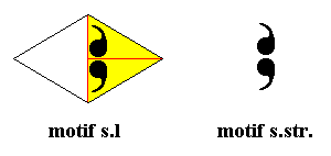
Figure 48. Motif sensu lato and motif sensu stricto of the pattern representing the subgroup under investigation (Figure 47). The motif consists of two parts that are related to each other by a horizontal mirror line (which is also a symmetry transformation of the whole subgroup pattern).
The group elements of our Cm subgroup can in several ways be represented by corresponding areas in the above depicted Cm pattern :

Figure 49. Three ways to represent a group element of our Cm pattern. Each way should also include its mirror image, in order to represent all elements of the group (which in our case is a subgroup of the group C2mm). In the next Figure we have chosen the third way.
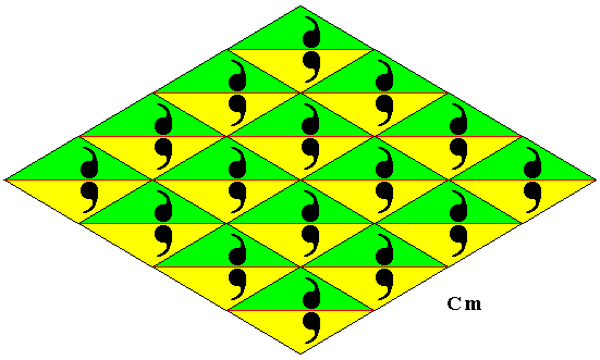
Figure 50. A possible way (third way in the previous Figure) to represent group elements by areas (green or yellow). If done in this way, any such area representing a group element is at the same time a f u n d a m e n t a l r e g i o n of the pattern representing the group Cm . Such a region tiles the plane without leaving gaps. In the present Figure the colors green and yellow do not signify symmetry or antisymmetry features. They only serve to highlight the areas representing group elements.
In order to let the group elements and the areas representing them as fundamental regions come out clearly, we explicitly identify some elements :

Figure 51. Group elements represented by fundamental regions (green or yellow). Some group elements have been explicitly named in terms of the generators of the (sub)group.
These generators are : The translations tx and ty (See Figure 47 ) and the reflection in the line m . These (and all their combinations) are also elements of the full group (C2mm) where tx is denoted by tne , ty by tse and m by mh (See Figure 5 of Part XXIII ).
The colors green and yellow do not signify (anti)symmetry features. As always, the pattern must be imagined to extend indefinitely over the plane.
In the next document we will give some examples of antisymmetry patterns, derivable from C2mm patterns, and present in Neolithic ornamental art.
e-mail : 
To continue click HERE for further group theoretic preparation to the study of the structure of three-dimensional crystals (crystallography) and the basic symmetry of organisms (promorphology).
Back to 3-dimensional crystals (conclusion), Organic Tectology and Promorphology
Back to subpatterns and subgroups (introduction)
Back to subpatterns and subgroups Part II
Back to subpatterns and subgroups Part III
Back to subpatterns and subgroups Part IV
Back to subpatterns and subgroups Part V
Back to subpatterns and subgroups Part VI
Back to subpatterns and subgroups Part VII
Back to subpatterns and subgroups Part VIII
Back to subpatterns and subgroups Part IX
Back to subpatterns and subgroups Part X
Back to subpatterns and subgroups Part XI
Back to subpatterns and subgroups Part XII
Back to subpatterns and subgroups Part XIII
Back to subpatterns and subgroups Part XIV
Back to subpatterns and subgroups Part XV
Back to subpatterns and subgroups Part XVI
Back to subpatterns and subgroups Part XVII
Back to subpatterns and subgroups Part XVIII
Back to subpatterns and subgroups Part XIX
Back to subpatterns and subgroups Part XX
Back to subpatterns and subgroups Part XXI
Back to subpatterns and subgroups Part XXII
Back to subpatterns and subgroups Part XXIII